I think those settings are just holdovers from old-school applications - if the trigger wheel had a trigger for every cylinder's TDC position (and it was sensing directly off that trigger pulse rather than the coil drive pulse) or if there was a distributor in effect, the signal would have a pulse at every cylinder's TDC (or every other TDC) so the count would have to be divided by # of cylinders in that case.
However it will be rare these days and most applications (anything within at least last 20 years for most part) will be detecting at the coil (or the equivalent in a direct output for OEM tach from the ECU) at either one pulse per revolution (wasted spark or 2-stroke) or one pulse
every other revolution for non-wasted spark 4-stroke (in which case the resultant rpm is actually twice that of the detected frequency of pulses).
Most bikes are simply going to look at the signal to one coil - which is effectively the same as if it was single cylinder bike (only caveat being if it was indeed a wasted spark system).
So for coil signal system either 1 pulse 1 revolution or 1 pulse 2 revolutions are going to be the common settings - and indeed on the K bikes it is going to be 1/1 for both 3 & 4 cylinders.
Note that most 4-strokes will typically mark the TDC for cylinder #1 and since that is on the Crank, will be on every revolution. And then the ECU will determine the timing and on which cycle to fire if NOT wasted spark.
Consider a fictional 3 cylinder machine that has a trigger wheel that detects the TDC of EACH of the three TDC events (one for each cylinder);
if you were to look at that Trigger detector (crank position sensor), then you would have three pulses for every revolution. So if using this signal for the tach, you would indeed have to divide by three.
But on same bike, with three separate coils, the ECU will decode that signal and ONLY send the reference from the appropriate TDC to the appropriate coil i.e. the coil for say cyl 1 does not see pulses when the other two cyls are at their own TDC. So if you detect the coil signal, it really is detecting only one pulse per engine revolution (although on some bikes the ECU may also have timed it down to only a pulse on the firing stroke when NOT wasted spark).
'Most' ECU and CPS will only mark the #1 TDC and the ECU computes the timing for the other cylinders.
This is getting off-subject a bit, but you may find this interesting -
so generally the ECU does not know from the Crank Position Sensor alone, whether each TDC is at top of compression stroke or exhaust stroke; (on the BMW K's, it actually doesn't matter or 'need' to know);
On many cars (& some bikes) they determine the firing cycle by also looking a CAM position sensor, so can tell from that which cycle is on;
on First generation Triumph EFI (1997) they utilized a French Sagem ECU - this was actually pretty sophisticated in how it determined the cycle;
no Cam sensor! But the Crank Position sensor not only has the TDC trigger (longer tooth), there are also evenly spaced teeth all around the trigger wheel that also feed pulses to the ECU and it computes the relatively minute difference in rate of change of speed (aka acceleration) and so can tell which is the power stroke!
The next generation of bikes used Keihin ECU and these do not have a cam sensor either - these have a MAP sensor which measures pressure in the intake (throttle body below the throttle plate) - it again detect the difference in pressure (vacuum) on the intake stroke so uses that to determine the correct cylinder timing. It's actually again very sophisticated in that although there is only ONE common MAP sensor (with a 3-way TEE connecting to the three TB's) the ECU knows which intake pressure relates to which cylinder as it is timed in relation to the Crank Position Sensor (the low pressure reading following #1 TDC MUST be the intake stroke for that cylinder; following the next #1 TDC 360 crank deg later, it will not have a low pressure following that position on that stroke)
All very clever stuff!
Sorry for distraction - normal programming will now be resumed

And again in summary, treat the K bike like a single cylinder 2-stroke as far as the Tach signal goes


 Speedo Wiring Help In Colorado? Tue Aug 07, 2018 3:02 pm


 :
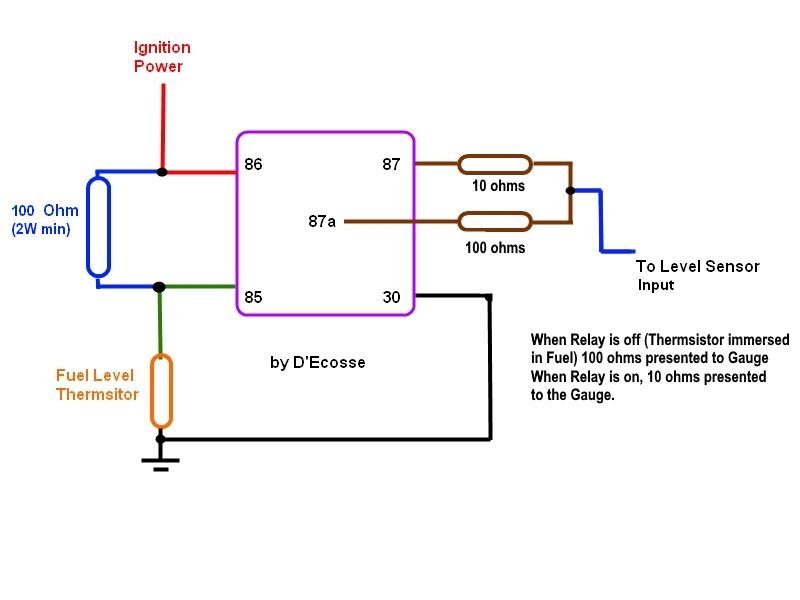
: . Ground is Brown (Gnd). In my document, I think you have Version 3 wiring.