BMW K bikes (Bricks)


You are not connected. Please login or register

View previous topic View next topic Go down  Message [Page 1 of 1]


louis0852

louis0852
active member
active member
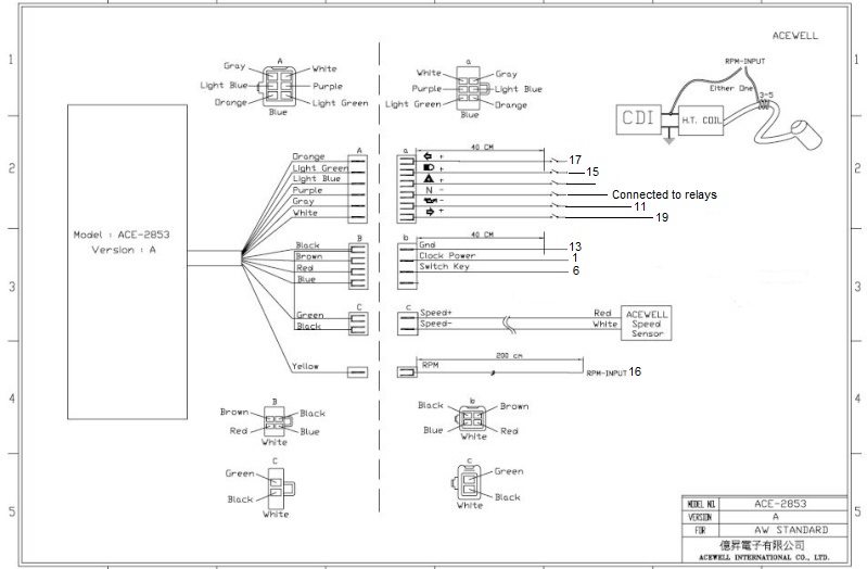
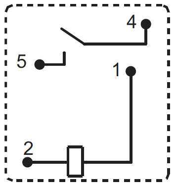
This is what I have so far...


What I need is:


Neutral light working as with old cluster

Hazard light working as engine warning light

Oil Temp light working as with old cluster


Additional Red LED as water temp light

Additional Orange LED as hazard flasher light

Help on Wiring Acewell ACE-2853 with K75? Acewel10
Help on Wiring Acewell ACE-2853 with K75? Img_7910
Help on Wiring Acewell ACE-2853 with K75? Img_7911
Help on Wiring Acewell ACE-2853 with K75? Img_7912
Help on Wiring Acewell ACE-2853 with K75? Pin_al10
Help on Wiring Acewell ACE-2853 with K75? Wiring10


Inge K.

Inge K.
VIP
VIP
louis0852 wrote:Neutral light working as with old cluster
PM received and answered.

louis0852 wrote:Hazard light working as engine warning light
These bikes haven't got a engine warning light, you can use it as a charge
warning lamp.....connect to pin 6 & 9 in old connector

louis0852 wrote:Oil Temp light working as with old cluster
Then you must add a sensor for this, you can use it as a low oil pressure
warning lamp......Connect to pin 6 & 11 in old connector.

louis0852 wrote:Additional Red LED as water temp light
Connect to pin 6 & 10 in old connector.

louis0852 wrote:Additional Orange LED as hazard flasher light
Connect to one of the flasher warning lamps, other end to the yellow/violet
wire at the hazard switch.

---------------------------------------------------------------------------------------
I'll guess you allready know.........LEDs must have correct polarity, they only functions with the current flow in one direction...not the other.
It's LEDs also in the Acewell.


__________________________________________________
Inge K.
K100RS -86. (first owner), K1100LTSE -94.
    

louis0852

louis0852
active member
active member
Thanks for the quick reply.

Just a question on the pins again, why is it that pin 13 and pin 18 are both grounds and should they be looped to one another?

With regards to the solid state relays. I read in another post on this forum that it could pose a problem that the relays which I have installed are AC instead of DC?


Inge K.

Inge K.
VIP
VIP
Pin 13, 18 & 23 is grounding different this and that in the old cluster, but all of
them is also connected together internally....13 is main, use this on the Acewell.

I also did remember that it was some problem using the solid state relays,
had the idea to mention it....but did forget that.  Rolling Eyes


__________________________________________________
Inge K.
K100RS -86. (first owner), K1100LTSE -94.
    

louis0852

louis0852
active member
active member
Will have a look once complete if the solid state AC relays work or not, if not will resort to the DC ones. Did source a few of them from the electronics store. Thanks again, will keep you up to date on the progress


Inge K.

Inge K.
VIP
VIP
Here is which pinout to use from the old cluster connector:


Help on Wiring Acewell ACE-2853 with K75? Acewel10


__________________________________________________
Inge K.
K100RS -86. (first owner), K1100LTSE -94.
    

robmack

robmack
Life time member
Life time member
Solid state relays will have voltage dropped across the "contacts" and are best avoided.  Use PC mount mechanical relays instead.  You can get them with the same form-factor as SS relays.  The current draw and operating voltage for the neutral detect circuit is minimal, giving you much choice in the size of the final board.  Just make sure the coil voltage is 12V DC.


__________________________________________________
Robert
1987 K75 @k75retro.blogspot.ca
http://k75retro.blogspot.ca/
    

louis0852

louis0852
active member
active member
robmack wrote:Solid state relays will have voltage dropped across the "contacts" and are best avoided.  Use PC mount mechanical relays instead.  You can get them with the same form-factor as SS relays.  The current draw and operating voltage for the neutral detect circuit is minimal, giving you much choice in the size of the final board.  Just make sure the coil voltage is 12V DC.

Hi robmack, is it possible for you to give me a complete description of what to ask for from the electronics store?

 Edited: Just to add to my above post. The company I will be buying from is communica, their website is  www.communica.co.za


Inge K.

Inge K.
VIP
VIP
This relay I think would be a good one for your Project.....a really small one.
But they won't tell you the price........... :suspect: .


__________________________________________________
Inge K.
K100RS -86. (first owner), K1100LTSE -94.
    

louis0852

louis0852
active member
active member
Will give them a call on monday to find out the prive and availability. Thanks again. Will keep the posts coming if problems should arise or when i succeed


Inge K.

Inge K.
VIP
VIP
If it turn out to be very expensive.......it shouldn't be any problem to find a alternative.


__________________________________________________
Inge K.
K100RS -86. (first owner), K1100LTSE -94.
    

robmack

robmack
Life time member
Life time member
This will also work if the one Inge referred is not available or too expensive.  At least this one has a price.  Heh, this company is like Rolls Royce -- if you have to ask the price, you can't afford us. affraid 

You're looking for 12VDC coil, max 1A DC contact rating, Form 1C (SPDT).  Fairly simple and straightforward.


__________________________________________________
Robert
1987 K75 @k75retro.blogspot.ca
http://k75retro.blogspot.ca/
    

louis0852

louis0852
active member
active member
Hi again, just need a little bit of advice regarding my new relays. I went for the inge k suggested. Please can someone have a look at the datasheet and help me with a wiring diagram. I would like the same layout as my first post bit obviously connecting the right pin numbers to the right relays and wires. Thank you in advance


duck

duck
Life time member
Life time member
Get a 9V transistor battery and a couple of test leads.  Try pairs of pins until you hear a small click.  That will tell you which terminals trigger the relay.  Then connect a continuity checker or ohmmeter to various other terminals while triggering it to determine which terminals the relay connects when triggered.


__________________________________________________
Current stable:
86 Custom K100 (standard fairing, K75 Belly pan, Ceramic chromed engine covers, paralever)
K75 Frankenbrick (Paralever, K11 front end, hybrid ABS, K1100RS fairing, radial tires)
86 K75C Turbo w/ paralever
94 K1100RS
93 K1100LT
91 K1
93 K75S (K11 front end)
91 K75S (K1 front end)
14 Yamaha WR250R
98 Taxi Cab K1200RS
14 K1600GT
http://www.ClassicKBikes.com
    

Inge K.

Inge K.
VIP
VIP
On the page I did link to, it was some additional info in pdf format.


Single relay, form A - 1,2 coil - 4,5 contacts....or does yours look different?


__________________________________________________
Inge K.
K100RS -86. (first owner), K1100LTSE -94.
    

robmack

robmack
Life time member
Life time member
The relay you bought has the following pinout:

Help on Wiring Acewell ACE-2853 with K75? 1forma10
What you are looking at here is the bottom of the relay and the relative positions of the pins.  In this diagram, the relay contacts are Pins 4 and 5, the energizing coil is pins 1 and 2.

On your current schematic, you have the following pin designations:
1 and 2 are leads for the solid state relay's contact pair
3 and 4 are the energizing leads.

The leads map in the following way:
Old SS RelayNew micro relay
Pin 1Pin 5
Pin 2Pin 4
Pin 3Pin 1
Pin 4Pin 2

You now have enough information to wire up your new circuit.


__________________________________________________
Robert
1987 K75 @k75retro.blogspot.ca
http://k75retro.blogspot.ca/
    

louis0852

louis0852
active member
active member
Just a quick update on that wiring. What I've managed so far is a new set of relays, automotive ones which IngeK suggested and the pin layouts robmack pointed out. So this is my as built circuit board.


Help on Wiring Acewell ACE-2853 with K75? Wiring13

Help on Wiring Acewell ACE-2853 with K75? Pin_al11

As well as the as wired pinout connections on the bike. I have the following issues with the speedo:

Oil light stays on
Neutral does not light up, but have tested that the LED within the speedo works so must be my circuit board.

With regards to the circuit board and when it is connected, I have noticed that the fuel level on the speedometer shows full when in Neutral, when in first gear shows empty with last bar flashing, when in second gear three bars, and so on.

Any advice will be helpful as I have tried numerous things with no success so far.


robmack

robmack
Life time member
Life time member
louis0852 wrote:Oil light stays on
You have the connection correctly wired as far as I can tell.  The Brown/Green wire that went to Pin 11 on the old speedo is wired directly to Gray wire on the Acewell.  When the oil pressure is too low, the switch closes and lights the LED.  I would guess a defective switch or wiring is shorted to ground somewhere between the oil pressure switch at the pump and the Acewell.

louis0852 wrote:Neutral does not light up, but have tested that the LED within the speedo works so must be my circuit board.
Pin 2 on R4 should be grounded.  You have it going to Pin 5 Black.  Remove the Brown Pin 18 wire on R4 Pin 1 and move it to Pin 2.
Pin 4 on R3 should have a diode connected to it.  The cathode of the diode goes to Pin 4 and the anode goes to Pin 5 Black.

louis0852 wrote:With regards to the circuit board and when it is connected, I have noticed that the fuel level on the speedometer shows full when in Neutral, when in first gear shows empty with last bar flashing, when in second gear three bars, and so on.

Any advice will be helpful as I have tried numerous things with no success so far.
Can't fathom this failure.  You haven't indicated how you've connected the fuel level sender to the gauge.  There is no online information from Acewell to help me either.


__________________________________________________
Robert
1987 K75 @k75retro.blogspot.ca
http://k75retro.blogspot.ca/
    

Inge K.

Inge K.
VIP
VIP
robmack wrote: You haven't indicated how you've connected the fuel level sender to the gauge.

The level gauge is connected to the low level warning switch.

In the "adjusted" Acewell diagram I did post I deleted the wire to the gauge
as it won't function with our level sender....the resistance goes in the opposite direction.


__________________________________________________
Inge K.
K100RS -86. (first owner), K1100LTSE -94.
    

louis0852

louis0852
active member
active member
So I have managed to get the neutral light on the Ace working to an extent. And as stupid as it may sound, I in my infinite wisdom managed to swop the connectors, which look similar in my defence, of the gear indicator switch and the fuel level switch. This would explain my fuel level on the ace indicating through bars, which gear I am in.

As for the neutral light:

The light is on regardless if I am in neutral or not. I have run through all the gears while stationary and the neutral light remains on through all five gears.
The following is the circuit drawing of how it is currently connected as robmack suggested. Where I am left with questions is regarding Pin1 on R4 and if it should be connected to something? And if the connection between Pin4 R3 and Pin1 R4 should remain the same or change. Win2 on R4 I have made a mistake on earlier drawing, where I referred to brown going to Pin18 and then on another drawing showing Pin13 and so on, I would assume Pin13 to be the ideal ground to connect to? As for the rest, please indicate if they are still correct?

Thanks
Help on Wiring Acewell ACE-2853 with K75? Wiring15


robmack

robmack
Life time member
Life time member
The diode is backwards.  My apologies for having misled you by mixing up anode and cathode.  Always good to refer to the original schematic for this relay circuit.

Pin 1 on R4 only connects to Pin 4 R3.  The wire labelled "???" no longer exists since you moved it to Pin 2.

Are you 100% certain that the relays you bought are 1FormA (SPST-NO) relays?  There's no possibility that the contacts are normally closed, is there?  Did you double-check that the contacts close when the relay is energized?


__________________________________________________
Robert
1987 K75 @k75retro.blogspot.ca
http://k75retro.blogspot.ca/
    

louis0852

louis0852
active member
active member
robmack wrote:The diode is backwards.  My apologies for having misled you by mixing up anode and cathode.  Always good to refer to the original schematic for this relay circuit.

Pin 1 on R4 only connects to Pin 4 R3.  The wire labelled "???" no longer exists since you moved it to Pin 2.

Are you 100% certain that the relays you bought are 1FormA (SPST-NO) relays?  There's no possibility that the contacts are normally closed, is there?  Did you double-check that the contacts close when the relay is energized?
I had the diode the right way, with the bigger black part on the black wire and the smaller grey part on Pin4 R3. I did however swop it around just in case, but with no result, no lit Neutral light. Turned it back again and same problem. Neutral light on regardless of gear position.
The relays I bought are most definitely 1FormA. I have checked the contacts are closed when energized.

Sorry for the hassle though, any further suggestions?


robmack

robmack
Life time member
Life time member
Minor observation but Yellow should go to Piin 2 on R1, and Blue to Pin 2 R3 to be absolutely true to the original design.  It shouldn't affect the operation though.

You'll have to test each stage of your circuit.  The theory is this.  Relays R1, R2 and R3 form a simple 3-input logical NAND gate.  Relay R4 inverts the start enable signal for the Neutral light.  Power is fed to all three coils and to R1's contact.  When the TGP switch grounds its input, R1 energizes and power is fed to R2's contact.  Same thing for R2, it feeds power to R3's input.  When all three inputs on TGP switch are grounded (Neutral position), then power is fed to the coil on R4 and energizes it.  Power is simultaneously fed through the diode to the Start Enable circuit.  Because R4 now has power on one side of the coil and the other side is grounded, the coil energizes.  Ground is presented on Pin 5 and the LED in the instrument cluster lights up.

If the LED is on constantly, then its input is somehow constantly grounded.  The assumption here is that Acewell wants the Purple wire grounded to light the LED. That's the reason for the "N-" designation on the Acewell circuit diagram. Test the LED's operation by grounding the Purple wire on the Acewell with the relay circuit disconnected.  Open = LED extinguished; Grounded = LED illuminated.

Bench test your circuit.  Apply a power source to the circuit and ground each input in turn, testing for power on Pin 4 for each relay as you test it in turn.  Start with R1, then R2 (while R1 energized) then R2 (while R1 and R2 energized).  With all three inputs grounded, you should see power on Pin 1 of R4.

Hope that helps a bit.


__________________________________________________
Robert
1987 K75 @k75retro.blogspot.ca
http://k75retro.blogspot.ca/
    

louis0852

louis0852
active member
active member
robmack wrote:Minor observation but Yellow should go to Piin 2 on R1, and Blue to Pin 2 R3 to be absolutely true to the original design.  It shouldn't affect the operation though.

You'll have to test each stage of your circuit.  The theory is this.  Relays R1, R2 and R3 form a simple 3-input logical NAND gate.  Relay R4 inverts the start enable signal for the Neutral light.  Power is fed to all three coils and to R1's contact.  When the TGP switch grounds its input, R1 energizes and power is fed to R2's contact.  Same thing for R2, it feeds power to R3's input.  When all three inputs on TGP switch are grounded (Neutral position), then power is fed to the coil on R4 and energizes it.  Power is simultaneously fed through the diode to the Start Enable circuit.  Because R4 now has power on one side of the coil and the other side is grounded, the coil energizes.  Ground is presented on Pin 5 and the LED in the instrument cluster lights up.

If the LED is on constantly, then its input is somehow constantly grounded.  The assumption here is that Acewell wants the Purple wire grounded to light the LED. That's the reason for the "N-" designation on the Acewell circuit diagram. Test the LED's operation by grounding the Purple wire on the Acewell with the relay circuit disconnected.  Open = LED extinguished; Grounded = LED illuminated.

Bench test your circuit.  Apply a power source to the circuit and ground each input in turn, testing for power on Pin 4 for each relay as you test it in turn.  Start with R1, then R2 (while R1 energized) then R2 (while R1 and R2 energized).  With all three inputs grounded, you should see power on Pin 1 of R4.

Hope that helps a bit.

Thanks a lot robmack, at least I know the theory behind its operation now so that I can trouble shoot the circuit. Will test in the morning and get back to you. If it operates as it should it only leaves the gear indicator switch at the rear of the gearbox.


louis0852

louis0852
active member
active member
So I still cannot manage to get the neutral light to switch off. Is the black to Pin5 from R3 Pin4 positive or negative? and is the positive side of the diode suppose to connect to the Black wire or to Pin4 R3? I have tested something on the bikes wiring in the meantime. I've tested continuity from each of the gear switch's cable, Pin 2-4 to ground on the bike and I only get readings once not in neutral. Does this not mean that the relays that I am suppose to use should be normally closed?


robmack

robmack
Life time member
Life time member
Let's look at the original circuit diagram.
Help on Wiring Acewell ACE-2853 with K75? Gpiemu1
The first three relays are wired the same:  Power to Pin 30, Output on Pin 87, Energizing power on Pin 86 and control on Pin 85.  The TGP switch truth table is binary coded decimal output.  It has three output wires and a ground. It will ground the output corresponding to the binary number it wants to represent.  For example, Gear 5 = Binary 101, meaning Yellow-Black will be grounded and the other two wires open-circuit.  To answer your second question, this schematic of the inside of the TGPI switch shows how it works:

Help on Wiring Acewell ACE-2853 with K75? Gear%2520position%2520Switch%2520internal%2520conn[/size]


When an output is open-circuit, no current flows and the relay is not energized.  When the output is grounded, current flows through the coil and the relay contacts close.  Since the relays are cascaded in series, as each relay energizes in turn, it provides power to the next relay in line.  Finally when all three relays get energized, power is presented to the Start Enable circuit.  The diode has to face in a direction of current flow -- from the relay #3 to the start circuit.  To answer your first question, Black to Pin 5 is an INPUT wire and has no polarity.  It expects to see a POSITIVE +12V signal on that wire for the starter to work.


Simultaneously, power is presented to Relay 4.  Relay 4 just inverts the signal and makes the +12V output into a grounded output.  This grounded output illuminates the LED.


__________________________________________________
Robert
1987 K75 @k75retro.blogspot.ca
http://k75retro.blogspot.ca/
    

louis0852

louis0852
active member
active member
I have come to an alarming conclusion that couldve saved me hours of work. The gear indicator switch on the back of the gearbox is faulty. It seems that both the yellow and black(pin3) and yellow and blue(pin4) work perfectly but that yellow and white(pin2) does not work at all. I have bridged pin 2 and pin 3 and the circuit works perfectly accept that in 4th gear neutral lights up again. My question now is how to rectify the switch problem or to just replace it?


robmack

robmack
Life time member
Life time member
Try opening the switch and cleaning it.  Check out Bert's rebuild page (http://hrsbstaff.ednet.ns.ca/bvogel/K100/K100.htm) for pictures of how he did this.


__________________________________________________
Robert
1987 K75 @k75retro.blogspot.ca
http://k75retro.blogspot.ca/
    

louis0852

louis0852
active member
active member
I just need to say a thank you, IngeK and Robmack for all the help with the neutral light problem. Managed to open up the GPI switch and found the one Spring pin was broken and no contact mustve happened for a long time. Cleaned it up, inserted a new spring contact pin just underneath the factory one ass I could not source a spring of that size. Today I cleaned up the wiring mess that consumed the bike. Everything placed underneath the tank in watertight aluminium boxes. Here are some pictures including the control console plate I made.
Help on Wiring Acewell ACE-2853 with K75? Img_8011
Help on Wiring Acewell ACE-2853 with K75? Img_8012
Help on Wiring Acewell ACE-2853 with K75? Img_8013


charlie99

charlie99
VIP
VIP
good work louis


__________________________________________________
cheezy grin whilst riding, kinda bloke ....oh the joy !!!! ...... ( brick aviator )

'86 K100 RT..#0090401 ..."Gerty" ( Gertrude Von Clickandshift ) --------O%O
'86 k100 rs.. #######..  "Fred " (f(rame) red ) ( Fredrick leichtundschnell ) - -
bits and pieces from many kind friends across the k100 world ...with many thanks ..
1987 k100rs ########   "Red"  - (red sports rs TWB style )
1989 K100rt #009637   "Black Betty"  (naked rt ala Nigel , now sporting an rs main fairing )
    

Inge K.

Inge K.
VIP
VIP
charlie99 wrote:good work louis

+1.  Help on Wiring Acewell ACE-2853 with K75? 112350  .


__________________________________________________
Inge K.
K100RS -86. (first owner), K1100LTSE -94.
    

robmack

robmack
Life time member
Life time member
+2.   Big thumb


__________________________________________________
Robert
1987 K75 @k75retro.blogspot.ca
http://k75retro.blogspot.ca/
    

charlie99

charlie99
VIP
VIP
might have a simple solution for the "neutral" indication soon ....for all those going away from original instruments

ill post up the details soon as I have it tested .


__________________________________________________
cheezy grin whilst riding, kinda bloke ....oh the joy !!!! ...... ( brick aviator )

'86 K100 RT..#0090401 ..."Gerty" ( Gertrude Von Clickandshift ) --------O%O
'86 k100 rs.. #######..  "Fred " (f(rame) red ) ( Fredrick leichtundschnell ) - -
bits and pieces from many kind friends across the k100 world ...with many thanks ..
1987 k100rs ########   "Red"  - (red sports rs TWB style )
1989 K100rt #009637   "Black Betty"  (naked rt ala Nigel , now sporting an rs main fairing )
    

robmack

robmack
Life time member
Life time member
Interesting Charlie.

I'm in the process of redesigning my gear indicator display board, because I was asked to produce several examples for a company.  I'll also post up details about this in the other thread I started when things are ready.


__________________________________________________
Robert
1987 K75 @k75retro.blogspot.ca
http://k75retro.blogspot.ca/
    

Finnigan

Finnigan
Silver member
Silver member
any updates on the simple neutral light fix?


__________________________________________________
1990 k100LT
    

Inge K.

Inge K.
VIP
VIP
About your question in "Motobrick", have a look in this thread.


__________________________________________________
Inge K.
K100RS -86. (first owner), K1100LTSE -94.
    

robmack

robmack
Life time member
Life time member
Finnigan wrote:any updates on the simple neutral light fix?
https://www.k100-forum.com/t8465-gearshift-decoding-for-aftermarket-instruments


__________________________________________________
Robert
1987 K75 @k75retro.blogspot.ca
http://k75retro.blogspot.ca/
    

Finnigan

Finnigan
Silver member
Silver member
After wiring up the neutral light fix with the diagram below (3 relays) the neutral light comes on but I'm getting a buzzing sound from the starter relay whenever I try and start the bike.

I only did the 3 circled relays because the diagram I had didn't show the 4th.  Do i need to wire in the 4th to make it work?  I also took a picture of the relays i'm using, in case its the wrong rating.

Please help!

Help on Wiring Acewell ACE-2853 with K75? Neutra10

Help on Wiring Acewell ACE-2853 with K75? Photo-10


__________________________________________________
1990 k100LT
    

charlie99

charlie99
VIP
VIP
from memory,
you can get away with the 3 relays ....but  ...you need to install a diode from the last relay, but before the start button circuit 

I may be wrong but that makes sense to me ...so as to stop feedback to the rest of the power side of the ignition circuits


__________________________________________________
cheezy grin whilst riding, kinda bloke ....oh the joy !!!! ...... ( brick aviator )

'86 K100 RT..#0090401 ..."Gerty" ( Gertrude Von Clickandshift ) --------O%O
'86 k100 rs.. #######..  "Fred " (f(rame) red ) ( Fredrick leichtundschnell ) - -
bits and pieces from many kind friends across the k100 world ...with many thanks ..
1987 k100rs ########   "Red"  - (red sports rs TWB style )
1989 K100rt #009637   "Black Betty"  (naked rt ala Nigel , now sporting an rs main fairing )
    

Rick G

Rick G
admin
admin
If you don't put a diode in then every time you pull the clutch in the neutral light flashes.


__________________________________________________
"Man sacrifices his health in order to make money.
Then he sacrifices money to recuperate his health.
And then he is so anxious about the future that he does not enjoy the present; the result being that he does not live in the present or the future; he lives as if he is never going to die, and then dies having never really lived."   Dalai Lama


Bikes 1999 K1100 LT with a Big Block 1200
    

robmack

robmack
Life time member
Life time member
The circuit below is showing the diode placement.

Help on Wiring Acewell ACE-2853 with K75? Gpiemu1 Click on the diagram to go to the technical description.


__________________________________________________
Robert
1987 K75 @k75retro.blogspot.ca
http://k75retro.blogspot.ca/
    

charlie99

charlie99
VIP
VIP
good post rob    explains it well


__________________________________________________
cheezy grin whilst riding, kinda bloke ....oh the joy !!!! ...... ( brick aviator )

'86 K100 RT..#0090401 ..."Gerty" ( Gertrude Von Clickandshift ) --------O%O
'86 k100 rs.. #######..  "Fred " (f(rame) red ) ( Fredrick leichtundschnell ) - -
bits and pieces from many kind friends across the k100 world ...with many thanks ..
1987 k100rs ########   "Red"  - (red sports rs TWB style )
1989 K100rt #009637   "Black Betty"  (naked rt ala Nigel , now sporting an rs main fairing )
    

Finnigan

Finnigan
Silver member
Silver member
Good info guys I'll wire that up this weekend and tell you how it goes, thanks


__________________________________________________
1990 k100LT
    

Finnigan

Finnigan
Silver member
Silver member
I found a diode rated at 100v and 3A, would that work?


__________________________________________________
1990 k100LT
    

robmack

robmack
Life time member
Life time member
yes.


__________________________________________________
Robert
1987 K75 @k75retro.blogspot.ca
http://k75retro.blogspot.ca/
    

Sponsored content


View previous topic View next topic Back to top  Message [Page 1 of 1]

Permissions in this forum:
You cannot reply to topics in this forum