BMW K bikes (Bricks)


You are not connected. Please login or register

View previous topic View next topic Go down  Message [Page 1 of 1]


1Back to top Go down   Hall effect sensor testing.  Empty Hall effect sensor testing. Wed Mar 30, 2016 9:16 am

Beamer

Beamer
Platinum member
Platinum member
Hi,

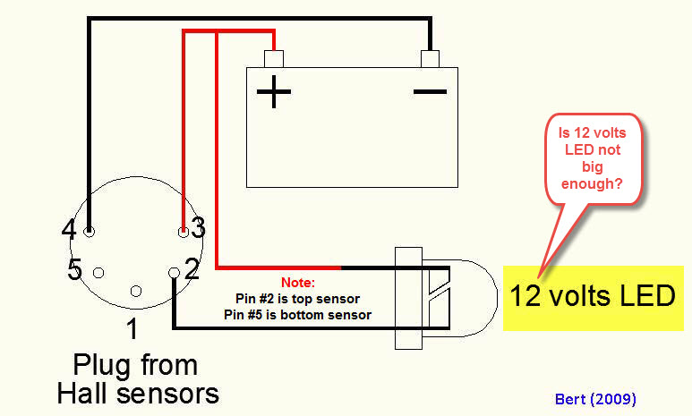
I have been referring to the excellent troubleshooting pdf provided by crazy frog in the portal section.

It shows the connection diagram to test the HES units. Essentially, this uses an LED in series with the open collector output transistor of the Honeywell integrated sensor and amplifier unit. However, the specsheet for the device says output can sink a maximum of 40mA. It is not clear to me how an LED will limit the current to that value.

In view of the price of these things, I don't want to be taking any risks ( without talking about the problems of being without transport until I can be delivered a replacement. ).

Is this test a safe thing to do ?

An LED is not a current limiter like a resistor. It will have a forward voltage drop of about 1.2V when lit up. This means that we need to consider what voltage battery in is being used to test and we should add a suitable series resistor to limit the current to < 40mA.

It is not indicated in the guide but it looks like it is supposed to represent the 12V bike battery.


My calculation:

(12 - 1.2 )V / 40mA = 270 ohm

This means that using less than that value ( eg. no resistance at all , as in the guide ) will likely blow the output transistor. At the very least you're on your own trying it since it would be wildly outside the safe range of operation depending up on what type of battery is used for the test.


I have seen similar schemes proposed on the internet, so I guess at least a few people are doing this kind of thing.

I've also seen articles where the power is connected backwards too, so I'm never sure if some of those writing this stuff have ever actually tries what they writing or whether they actually tested the unit on a bike afterwards.

Is there something I'm missing here, or is this test will a single LED in risk of damaging the unit under test?

TIA.

PS I have just noticed something in the guide. Despite having the electrical symbol for an LED, the label next to it says "12 volt LED".

Now LEDs do not exist as "12V" items. What I suspect this may be referring to is an LED replacement for a 12V dashboard incandescent bulb.  I have recently seem a friend who had bought such a plug-in replacement. Obviously, these must have a suitable limiting resistor hidden inside the plastic housing which makes it possible to plug them into a classic bulb holder on a bike.

So my conclusion is that the circuit given in the guide is INCORRECT and will cause people to destroy their expensive  HES units if taken as shown.

Crazy frog says up front that he in not an electronic engineer. so probably he did not appreciate the need for a limiting resistor, nor did he realise that "LED" in question is not JUST an LED and that the circuit he provided was not correctly representing what he had used.

He also calls for comments and corrections. So.....

Please specify :

1) Battery voltage in schematic.
2) Add a limiting resistor of at least 270 ohm to the circuit.
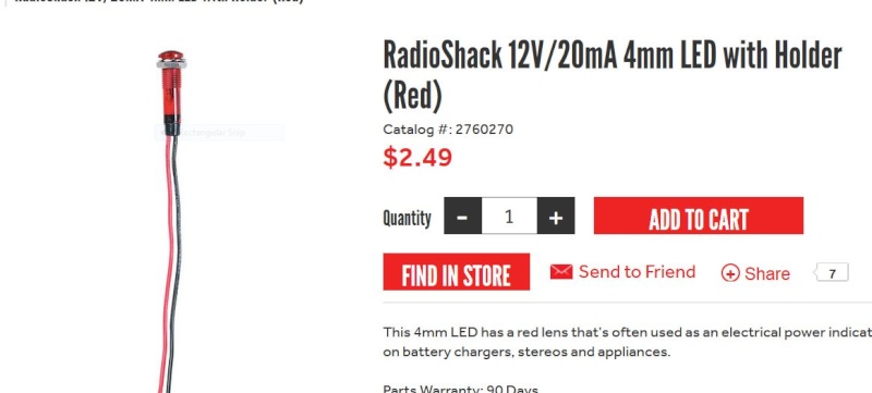
3) Add a note explaining that an LED dashboard bulb replacement can be used ( the resistance inside the 276-270 is 680 ohm. ).

The current limiting resistor in these LED units is there for similar reasons and will protect both the LED and the HES.


Sadly my units are already dead thanks to crap info supplied in another guide.


Last edited by Beamer on Wed Mar 30, 2016 4:20 pm; edited 1 time in total


2Back to top Go down   Hall effect sensor testing.  Empty Re: Hall effect sensor testing. Wed Mar 30, 2016 1:10 pm

brickrider2

brickrider2
Life time member
Life time member
These units are available for a very reasonable price outside the BMW distribution system.  In fact, there was a group buy organized here on this forum a few months ago.  A guide for their installation was also posted.


3Back to top Go down   Hall effect sensor testing.  Empty Re: Hall effect sensor testing. Wed Mar 30, 2016 2:57 pm

Beamer

Beamer
Platinum member
Platinum member
Thanks, I think I've got it. I'll check out the cost and delivery prices.

https://www.k100-forum.com/t9878-bulk-buy-hall-effect-sensors-closed


4Back to top Go down   Hall effect sensor testing.  Empty Re: Hall effect sensor testing. Wed Mar 30, 2016 3:05 pm

Beamer

Beamer
Platinum member
Platinum member
It seems that a lot of the confusion about the "LEDs" is caused by supplier like Radio Shack calling things LEDs which are not just LEDs and also totally failing  to mention that there is a resistance inside.

This is mad. The ref. provided by Crazy is 276-270

https://www.radioshack.com/products/radioshack-12v-20ma-4mm-red-led-with-holder

http://data-envelopment-analysis.ru/radioshack-12v-20ma-4mm-red-led-with-holder/2760270.html/alt__Y29taW5nc29vbi5yYWRpb3NoYWNrLmNvbQ

http://www.pbase.com/image/124447791

Somewhere on a forum someone has sussed that there is a resistor ( of unknow value ) . Why the heck the suppliers don't bother to mention that little detail is anyone's guess.

http://forums.parallax.com/discussion/142075/radio-shack-led-with-built-in-resistor


To run at 20mA at 12V means it will be fine to test the HES which can sink 40mA. (12-1.2)V / 20mA ; it's probably a 560ohm.

This resistor MUST be marked in the schematic, which currently shows connecting a bare LED. Doing that will almost certainly grill the HES at the first attempt when using a 12V bike battery.

Hopefully Crazy Frog will see this and update the otherwise excellent notes.


5Back to top Go down   Hall effect sensor testing.  Empty Re: Hall effect sensor testing. Wed Mar 30, 2016 3:36 pm

KJustin

KJustin
Silver member
Silver member
Beamer, I just happen to have one of those radio shack "LEDs" on hand.  The back of the packaging says that the resistor inside is 680 ohms (maybe they've upgraded the packaging recently?).  You can see the resistor inside and reading the color coding on the resistor (which is not completely easy becuse the plastic in which it is embedded is colored), 680 ohms is what's marked on the resistor.

I need to test my HES (I think I have a bad coil...I've got another thread going on that right now, but want to check the HES also) and was going to follow Crazy Frog's guide, but had some of the same questions as you.  I'm weak on electroinics, so didn't articulate as many questoins/issues as you had though. 

Anyway, assuming that the resistor is 680 ohms in this light, will this light work to test the HES?  And, is it safe to do so using the battery on the bike?  TIA!


__________________________________________________
1985 K100 Cafe Racer (formerly an RT), VIN 0051736
    

6Back to top Go down   Hall effect sensor testing.  Empty Re: Hall effect sensor testing. Wed Mar 30, 2016 3:45 pm

Beamer

Beamer
Platinum member
Platinum member
Thanks for the confirmation of the exact value.

680 ohm is the next std value up, and that will mean somewhat less than 20mA, so it's fine.

I've just tested a std. red LED with a 470 ohm resistor and it passes 23mA at 12.4V ( a fairly typical value for a well charged "12V" lead acid battery ).

So their so-called 12V / 20mA "LED" will pass a fair bit less than 20mA.

BTW I'm sure that the referenced product Crazy cited works as he described. The problem is that his schematic suggests this is done ONLY with an LED, and that is not the case. Doing so would blow the HES.

If you have the same thing he used, you are fine. Though you are right to be cautious when a little unsure of the details.


7Back to top Go down   Hall effect sensor testing.  Empty Re: Hall effect sensor testing. Wed Mar 30, 2016 4:22 pm

Holister

Holister
Life time member
Life time member
Beamer, probably best to PM crazy frog directly regarding your suggested ammendment.


__________________________________________________

1989 K100RT     VIN  0097367 (naked)  
1996 K1100RS   VIN  0451808
 Hall effect sensor testing.  Austra12    Fuel:  95 Octane
Engine Oil: Nulon Full Synthetic 15W50
Gear Box Oil:  Nulon Synthetic 75W90
    

8Back to top Go down   Hall effect sensor testing.  Empty Re: Hall effect sensor testing. Wed Mar 30, 2016 4:29 pm

Beamer

Beamer
Platinum member
Platinum member
Kaptain Holister wrote:Beamer, probably best to PM crazy frog directly regarding your suggested ammendment.
Yes, I've already done that. Wink


9Back to top Go down   Hall effect sensor testing.  Empty Re: Hall effect sensor testing. Wed Mar 30, 2016 5:01 pm

Crazy Frog

Crazy Frog
admin
admin
Please re-read the testing procedure and particularly the yellow frame stating the following:
WARNING:
The 12v LED could be substituted by a regular 2.5v-3v but a 470Ω resistor would have to be installed in series with the the LED


"However, the schematic you provide does not show the resistor As shown, this will blow the output transistor at the first attempt."

The schematic doesn't show a resistor because it is clearly indicated that the specific test uses a 12V LED (The one with a built in resistor).
If you want to use a common 2.5V-3V LED, you have to refer to the warning in the yellow frame
 Very Happy

You have to read the full instructions before starting to play with the electronic.
What would be the effect if had put a resistance on the schematic and you use a 12 Volts LED?
You would wrongly diagnose a faulty HES. Twisted Evil

Hall effect sensor testing.  K100_t10


__________________________________________________
Hall effect sensor testing.  Frog15Hall effect sensor testing.  Logo2101986 k75, 1985 K100rt, 1985 K100rt/EML GT2 sidecar, 1999 K1200lt/Hannigan Astro Sport sidecar.
    

10Back to top Go down   Hall effect sensor testing.  Empty Re: Hall effect sensor testing. Wed Mar 30, 2016 6:48 pm

Beamer

Beamer
Platinum member
Platinum member
Thanks for taking a look. That text in yellow is confused. That does not help.


WARNING: On the next test, never substitute the LED for a
bulb.
This should read 'never substitute a bulb for the LED'.


The 12v LED could be substituted by a regular 3v but a 470Ω resistor would have to be installed in series with the the LED
 LEDs are not rated in voltage. There is no such thing as a "12V" LED or a "3V" LED. They are specified primarily in terms of max current they can handle  (mA).

Spec sheets give a maximum permissible current in mA and a typical forward voltage drop ( 1.2 to 1.8 volt for a std red LED depending on how hard it is driven ; green ones start about 1.8V) . The current  is the main design criterion that must be respected, like the 40mA limit for the output transistor in the HES chip.

Some of the new very high-powered surface mounted "white" LEDs may need 3 to 4V to produce max light output. They are still current controlled devices, not "3V LEDs".

Don't be misled my mickey-mouse outfits like Radio Shack. At an electronics supplier, if they have an integrated resistor, it will be clear that they are not just LEDs.

http://uk.farnell.com/led-products

 
A regular round LED is usually 20mA and will cause a voltage drop of about 1.5 to 2V.

The main point which needs correcting is addition of a resistor in the circuit; be it a discrete component added to a std LED or the integrated resistor built into some "LED" packages; or a separate resistor inside the plastic lamp housing as in the case of the 276-270.

It should be shown in the circuit. 


That's what circuit diagrams are for. You do not miss an essential component out of a schematic and then say "it was left out because..." Schematics should be self-contained and complete, not dependant on a little yellow box on a previous page.

LED = light emitting diode , it does not have a resistor, it is a diode. It is not a "12V" LED. If you want to represent one of these devices in a schematic you need two symbols: the diode and the resistor.


I would happily add your comments and experience to this page if they are relevant.

I'm sure the reason you took considerable time putting all this together was to help other people fix their bikes. So don't mind when someone suggests it could be clearer and tries to avoid a situation which may result in someone fritzing their HES instead of testing it.


Thanks again for an excellent guide. It has already been very useful today and there's lots more I haven't needed yet.


Last edited by Beamer on Wed Mar 30, 2016 6:56 pm; edited 1 time in total


11Back to top Go down   Hall effect sensor testing.  Empty Re: Hall effect sensor testing. Wed Mar 30, 2016 6:55 pm

Beamer

Beamer
Platinum member
Platinum member
What would be the effect if had put a resistance on the schematic and you use a 12 Volts LED?
You would wrongly diagnose a faulty HES.
Which is why you need to be clear that this product is NOT a LED but a LED plus a built-in 680 ohm current limiting resistor.


12Back to top Go down   Hall effect sensor testing.  Empty Re: Hall effect sensor testing. Wed Mar 30, 2016 8:59 pm

Point-Seven-five

Point-Seven-five
Life time member
Life time member
Hey, Mr. F-ing know-it-all.   Why don't YOU write the correct test procedure for checking the Hall Effect Sensors????

Seems you've found problems with every other procedure that you've been able to find on the interweb.


__________________________________________________
Present: 1991 K100RS "Moby Brick Too"
 
Past:
1994 K75RT "Ilsa, She Wolf of the SS"
1988 K100RS SE "Special Ed"
1994 K75S "Cheetos"
1992 K100RS "Moby Brick" R.I.P.
1982 Honda FT500
1979 Honda XR185
1977 Honda XL125
1974 Honda XL125
1972 OSSA Pioneer 250
1968 Kawasaki 175
    

13Back to top Go down   Hall effect sensor testing.  Empty Re: Hall effect sensor testing. Wed Mar 30, 2016 9:14 pm

Crazy Frog

Crazy Frog
admin
admin
Thanks point-seven-Five. You posted your answer 1/2 of a second before I posted mine.
This is the first time that I got annoyed with a new member. I accept any reasonable comments but this one is going totally wrong.
Beamer wrote:
What would be the effect if had put a resistance on the schematic and you use a 12 Volts LED?
You would wrongly diagnose a faulty HES.
Which is why you need to be clear that this product is NOT a LED but a LED plus a built-in 680 ohm current limiting resistor.
This is the only document about the K100 electronic that has been written for the electronically uneducated K rider in 30 years. Obviously, you don't understand that this has to be put in a simple language for anybody not having electronic knowledge's.
Apparently, you are ready to rewrite it in technocratic incomprehensible language for most of the people not having studied Electronic and create confusion.
When you say that 12 volts LED don't exist, for common people, they will go to Radio Scrap and ask for this and will get what they need:
Hall effect sensor testing.  12_vol10
This page has been translated in multiple languages and read over 30,000 times. Nobody has ever questioned about a 12 volts LED. You are the first one and this is time to visit Radio Shack
Everybody with no previous experience were able to source what was needed.

As a computer network engineer previously working in mechanical engineering, I am trying to help people without experience in simple words and not using my professional language full of acronyms. I am not trying to impress with formulas or whatever. Just help the poor guy having problems with the K bike. we don't debate about technical words(even if they are misused), but we get to the root of the problems without making a fuss of it.
This test has been performed multiples times by people with common sense and nobody has ever complained to burn an HES.
sorry, I have a real pleasure helping people in need,but I cannot get into futile debates like this one.

Just use your common sense!

CF


__________________________________________________
Hall effect sensor testing.  Frog15Hall effect sensor testing.  Logo2101986 k75, 1985 K100rt, 1985 K100rt/EML GT2 sidecar, 1999 K1200lt/Hannigan Astro Sport sidecar.
    

14Back to top Go down   Hall effect sensor testing.  Empty Re: Hall effect sensor testing. Wed Mar 30, 2016 11:21 pm

blaKey

avatar
Life time member
Life time member
"Hey, Mr. F-ing know-it-all.   Why don't YOU write the correct test procedure for checking the Hall Effect Sensors????"

You aren't winning too many friends Mr Beamer...especially the very helpful people on that other Forum where you've posted similar thoughts.

Ya catch more flies with honey rather than vinegar!


__________________________________________________
Neil
K100RS 1986 RED!

Dress for the ride and the potential slide.
    

15Back to top Go down   Hall effect sensor testing.  Empty Re: Hall effect sensor testing. Thu Mar 31, 2016 4:14 am

Beamer

Beamer
Platinum member
Platinum member
point-seven-five wrote:Hey, Mr. F-ing know-it-all.


Crazy Frog wrote:Thanks point-seven-Five.


What happened to the squeaky clean forum rules? No cuss words,even masked ones, no offensive or aggregative tones.. be nice etc. etc. Instead you thank him!


This is the first time that I got annoyed with a new member.

Why on earth would you get annoyed? I'm trying to make a helpful suggestion. Don't take it a personal affront. I have said in multiple places that this guide is excellent. It is the only useful guide I was able to find ( Sadly I found it too late and had blown my HES units thanks to the crappy guide on the other forum ).

I'm not suggesting you make this super technical, just make it accurate.

It may well be that the other guide got the idea from here. What I could not work out when I saw his photo of the "LED" connected and lit up was that it looked like a standard 5mm LED. I know this would blow the HES so I added a suitable resistor but your average Joe will just buy a "LED" and take out the  output of the  HES.

It's important to name things properly and to provide accurate schematics. Now if you don't want to do that we're not going to argue about it. I know enough not to get caught out.

 If you are going take any suggestions as an attack on your professional competence I'm not going to insist any further. I was impressed by the thoroughness of the guide and as a note of thanks wanted to contribute to improving it.


Don't get annoyed about it.


16Back to top Go down   Hall effect sensor testing.  Empty Re: Hall effect sensor testing. Thu Mar 31, 2016 4:16 am

charlie99

charlie99
VIP
VIP
Crazy Frog wrote:
Just use your common sense!

CF
here, here ..!

well said, that man


__________________________________________________
cheezy grin whilst riding, kinda bloke ....oh the joy !!!! ...... ( brick aviator )

'86 K100 RT..#0090401 ..."Gerty" ( Gertrude Von Clickandshift ) --------O%O
'86 k100 rs.. #######..  "Fred " (f(rame) red ) ( Fredrick leichtundschnell ) - -
bits and pieces from many kind friends across the k100 world ...with many thanks ..
1987 k100rs ########   "Red"  - (red sports rs TWB style )
1989 K100rt #009637   "Black Betty"  (naked rt ala Nigel , now sporting an rs main fairing )
    

17Back to top Go down   Hall effect sensor testing.  Empty Re: Hall effect sensor testing. Fri Apr 01, 2016 2:04 pm

owrstrich

owrstrich
active member
active member
greetings...

i generraly donts come over here and invade your space...

butts in this case i gotts something to say...

whack whack whack whack whack whack whack...

j o


__________________________________________________
ΜΟΛΩΝ ΛΑΒΕ
http://www.motobrick.com
    

18Back to top Go down   Hall effect sensor testing.  Empty Re: Hall effect sensor testing. Fri Apr 01, 2016 6:23 pm

brickrider2

brickrider2
Life time member
Life time member
Now a that is a powerful argument for always wearing a helmet when you ride.  Shocked


19Back to top Go down   Hall effect sensor testing.  Empty Re: Hall effect sensor testing. Fri Apr 01, 2016 6:46 pm

Beamer

Beamer
Platinum member
Platinum member
trouble shooter wrote:Because of the injection time varying from 1.5ms to 9ms., it is best is to use an LED
to test the EFI computer output. A cheap regular LED should work for this purpose
but they are rated for 3.3v/20mA. A resistance would have to be installed in series
with the LED in order to drop the voltage to 3.3 volts. At some hobby stores (Radio
Shack, The Source..) you are able to buy 12V LED and with them, the resistor won't
be needed. The following schematic shows the testing at the fuel injectors.
(Red/Green and Yellow/Green are the 2 wires feeding each injector)

This, from the section about testing the injectors, is much clearer. There is also a schematic which includes a resistor, as I recommended.

For some reason when I suggested this, it is our of order, unnecessarily technical etc. etc. and makes crazy frogs even more crazy than they care to be.

Now I could point out that the point of the resistance is to limit the current, not to limit the voltage but I don't want to be accused of being technocratic or confusing those of lower intellect for whom this guide was apparently conceived. In essence the value or the resistor will do the job and guide is, once again, the best we have seen in 30 years. h/t to the frog for , I'll say it again, an excellent guide.

It is unfortunate that a suggestion that I made with the best intentions was taken the wrong way. Especially when the author did what I suggested for the HES section, in a later section of the guide anyway. Seems that I was not so far off after all.


Best wishes to all.

Now let's keep it civil, well mannered as the forum rules require. My grandma will be along later to check for any bad language. Shocked


20Back to top Go down   Hall effect sensor testing.  Empty Re: Hall effect sensor testing. Fri Apr 01, 2016 6:59 pm

blaKey

avatar
Life time member
Life time member
"confusing those of lower intellect for whom this guide was apparently conceived"

You never miss a chance at putting other people down to give your own ego a boost...


__________________________________________________
Neil
K100RS 1986 RED!

Dress for the ride and the potential slide.
    

21Back to top Go down   Hall effect sensor testing.  Empty Re: Hall effect sensor testing. Fri Apr 01, 2016 7:55 pm

Beamer

Beamer
Platinum member
Platinum member
wrong ego, mate.

That was crazy frog's reason for not posting an accurate description as I had requested.

Ironically it turns out that he had given a better description in a later section, That was what my last comment related to.

I too found that attitude a bit condescending. I don't see any reason why someone who is prepared to put their fingers into these devices cannot do a descent job provided they are given proper, clear and accurate information. It does not need dumbing down. Just stating accurately.

That was the motivation for my suggested improvements. So if you'll all get off my back, I came here to contribute to the common knowledge and filling in the lack of official information about these parts of these bikes.

My aim is not to trash Crazy's excellent guide but to improve it. It's good but it ain't perfect. Can we move on now?


BTW. Classy looking bike.


22Back to top Go down   Hall effect sensor testing.  Empty Re: Hall effect sensor testing. Fri Apr 01, 2016 9:03 pm

Rick G

Rick G
admin
admin
"confusing those of lower intellect for whom this guide was apparently conceived"

I do seem to recall that it was YOU who fried the hall sensors because you didn't use a 12 volt LED i.e. one that is suitable for use with 12 volts.
I would have thought that someone with such a scintillating interlect would have seen the problem long before the frying took place.
Once again we see evidence that light travels faster than sound.


__________________________________________________
"Man sacrifices his health in order to make money.
Then he sacrifices money to recuperate his health.
And then he is so anxious about the future that he does not enjoy the present; the result being that he does not live in the present or the future; he lives as if he is never going to die, and then dies having never really lived."   Dalai Lama


Bikes 1999 K1100 LT with a Big Block 1200
    

23Back to top Go down   Hall effect sensor testing.  Empty Re: Hall effect sensor testing. Fri Apr 01, 2016 9:37 pm

Crazy Frog

Crazy Frog
admin
admin
This topic is locked.
No more answer, is permitted.
Thanks for everybody expressing their opinion.

CF


__________________________________________________
Hall effect sensor testing.  Frog15Hall effect sensor testing.  Logo2101986 k75, 1985 K100rt, 1985 K100rt/EML GT2 sidecar, 1999 K1200lt/Hannigan Astro Sport sidecar.
    

Sponsored content


View previous topic View next topic Back to top  Message [Page 1 of 1]

Permissions in this forum:
You cannot reply to topics in this forum