1

 Bosch air flow meter restoration: summary Wed Apr 13, 2016 3:00 pm
Beamer
Platinum member

The previous thread on this subject involved questions, discussions and the process of discovery of how the Bosch air flow meter ( AFM ) worked and interacts with electronic control unit ( ECU )
The previous thread terminated here:
https://www.k100-forum.com/t10996p50-flowmeter-restoration#131627
Here I will try to condense it to a more coherent account.
Objective:
Determine whether the Bosch air flow meter ( AFM ) is defective; restore functionality; recalibrate rest position if moved during intervention or if recalibration is desired as a function of age, ie. find method to measure wiper position and re-adjust factory wiper calibration.
General description:
The Bosch AFM is based on a vane obstructing the air flow. The air flow into the inlet manifold pushes the vain against a return spring. Change in vane position displaces a potentiometer ( variable resistance ) and provides a voltage output, proportional to the volumetric air flow, to the ECU. This signal is used to control the volume of fuel injected by each fuel injector. A bypass screw controls the air flow through a bypass passage when the vane is closed under idle conditions.
There is also a thermistor ( temperature dependent resistor ) inserted into the air flow inlet. This acts as an air temperature sensor and forms part of the resistor chain that thus affects the output of the unit. This is a negative temperature coefficient device ( NTC ) whose resistance decreases with increasing temperature.
Construction detail:
The following image shows what it's all about: track wear due to years of a little cursor rubbing up and down each time the throttle is open or shut. How many million times has this moved in 20 odd years? I'm impressed with how long they last. This is a tribute to the rigorous design and top quality construction that german manufacturers are renown for. These are beautiful, precision instruments.
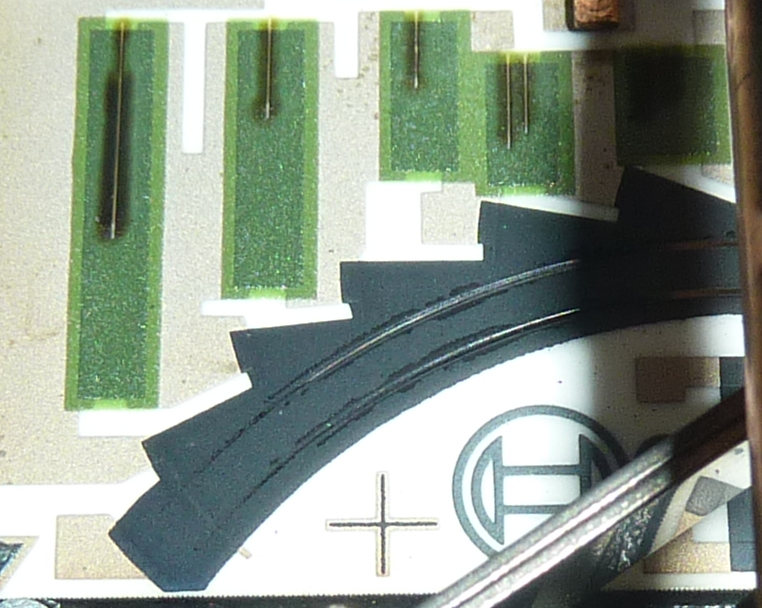
figure 1. Close up of track wear on Bosch AFM.
Though less clear in the photo, the dark lines on either side of wear mark tracks are a collection carbon power. This is easily blown off. This case of track wear is pretty typical of these units after 20y, not a case of extreme wear.
Note the usually sharp laser cuts in the green resistor blocks have gone fuzzy. This unit was badly stored. This is unusual degradation since on a K-bike they are well protected and usually look nearly new.
This is what the units look like inside. Comparison of early and later, factory modified, models are shown here:
https://www.k100-forum.com/t11043-bosch-air-flow-meter-version-differences
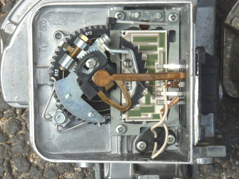
figure 2. General view of AFM internals.
There's loads of folklore out there about super accurate factory calibrations... don't evah touch this bit ... etc. The one thing that is factory precision calibrated at individual production item level is the value of the thick film resistors ( green rectangles ). These can not be mass produced to required accuracy and are individually laser trimmed to give a precise resistor chain providing a series of accurate voltage points along the black carbon strip where the copper wiper blade runs. This is the reference for the output. This calibration will not be lost by stripping and cleaning operations ( unless one is hamfisted and damages the unit ).
The preload of the multi-turn return spring is set to the nearest tooth during calibration. This is unlikely to require adjustment but should be marked if being removed. The preload, should it be lost is about 1.4 to 1.5 N.cm ; or 55 to 60 gram force applied at the lug behind the pinch bolt in the top left of the photo. It will be hard to start the motor if this is not very near the right position.
Because of the pre-load there is a certain amount of air which will pass through the bypass chamber when the vane is butted up against it's end stop in the closed, engine idle state. There is also typically a small movement of the vane possible before the output voltage changes. This is of the order of 1mm at the extremity of the vane. This movement will be referred to as dead zone in the following.
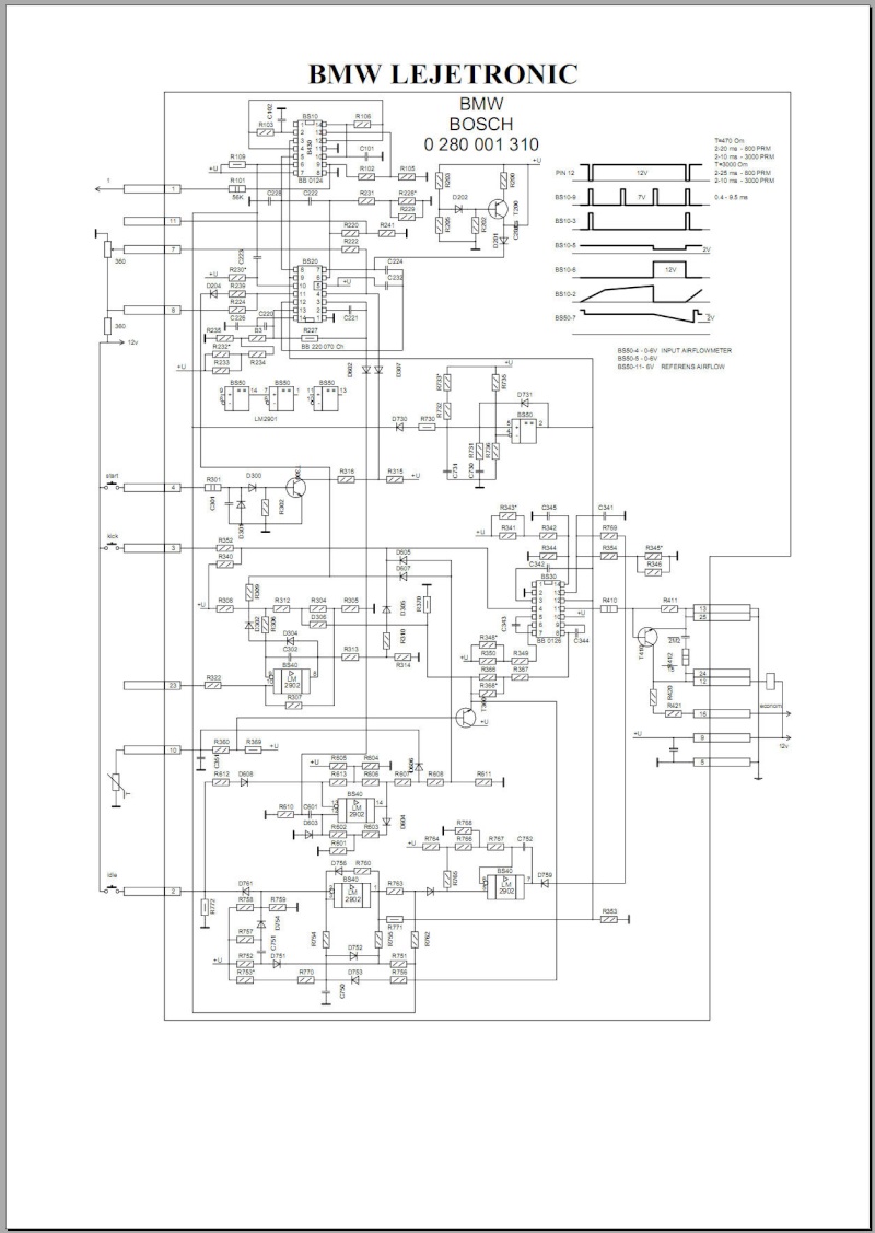
The ECU is totally analogue circuitry, not a micro-controller or 'computer' as many sources suggest. The circuit compares the output voltage of the AFM ( which is derived from the battery voltage ) with a fraction of the battery voltage. This gives it a degree of immunity from variations in the battery voltage. The inputs are buffered by integrated circuits ( operational amplifiers ) which draw minimal current. This means that resistance of the carbon track can be considerably higher than the low values of the lasers trimmed, fixed resistor chain, thus not affecting it. The carbon track just acts as in interpolation path between the set points of precision resistor chain. The resistance of the path is not critical since very little current is drawn. This is why testing the resistance of wiper contact externally is not an appropriate test. The contact pressure is intentionally very light to ensure longevity of carbon track. As a result the resistance can be very erratic.
Tests should be done with a voltage applied as under running conditions and the voltage at the wiper measured. Resistance measurements will not give a useful indication of the state of the AFM.
There are 12 resistors in the chain between pin 8 and pin 5 ( ground / chassis connection). Between pin 8 and pin 9 there are two more plus the thermistor temperature sensor. Battery voltage is applied at pin 9. This means that the thermistor modifies the resistor chain and thus the output, directly. This effectively applies a correction for changes in air density: it is the mass of air ( ie number of molecules ) which is relevant to the fuel requirement, not air volume.
The multi-turn return spring on the AFM provides a very linear ratio between angular deflection and applied torque. However, air flow through the flow meter varies approximately exponentially in relation to the vane deflection. For this reason, the resistor chain is arranged to have a logarithmic relation to position, the idea being that the output voltage will then be the log of the exponential: ie nearly a linear function of the volumetric air flow.
The following graph, using a logarithmic scale on x-axis shows that the output follows a log relationship over a wide range, then deviates somewhat towards fully opened positions. It is likely that gas flow is not truly exponential and this description is an over simplification. The unit will have been designed to return a good linear indicator of air mass flow.
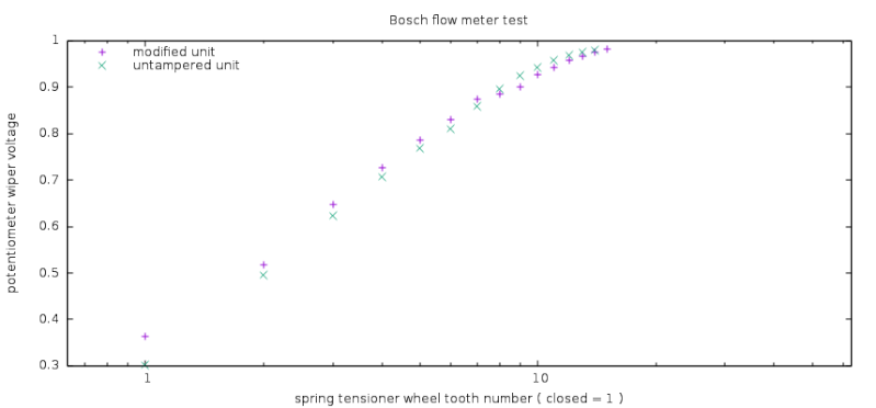
Figure 3. Logarithmic plot of potentiometer output against angular deflection. Data show both an unmodified, used unit and a modified unit under test. Output voltage is normalised and given as a ratio of the input voltage.
The bottom line test for the flow meter is the output voltage measured as a function of the force applied to the vane return spring. A physical set up for applying a measured torque is described below. Figure 4 shows a suspect unit under test and a known functional unit. It is readily seen that this unit will give a very bad signal to the ECU and cause very poor injection regulation. However, it does progress in a roughly monotonic fashion and this rather serious default probably would not be obvious without systematic measurements.
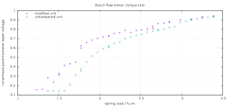
Figure 4. AFM output as a function of torque on return spring. Unit under test shows very erratic behaviour.
Recovering a reliable output signal:
If the carbon track is worn to the point of producing erratic output as shown in figure 4., a clean track must be recovered. This implies moving the copper wiper arm in relation to the metal plate carrying the resistor network. There are two principal ways to achieve this: a) move the track; b) move / bend the wiper arm.
Several sources suggest bending ( kinking ) the wiper arm to shorten it in order to find a new track. Others suggest raising or lowering the wiper arm height where it is clamped to the spindle. The major disadvantage of both these methods is that there is no control over the contact pressure of the wiper contacts on the carbon track. This will necessarily mean they end up with too much or too little pressure. It can be assumed that Bosch studied this quite closely in order to design the maximum lifetime whilst ensuring proper reliable electrical contact. Any ad hoc messing around with this arm will either be unreliable or lead to accelerated wear of the new track. Rather counter productive outcomes.
Option a) allows retaining the designed pressure by not distorting the wiper arm. The inconvenience is that it will disturb the calibration of the output in relation to the vane position. This can have a notable affect on mixture across the full range and needs to be correctly reset afterwards.
Moving the resistor plate.
Before removing the plate, it would be desirable to set up the recalibration procedure below and get a good calibration curve as a reference. This will save a lot of testing and tuning later. Also a score to mark the position of black plastic base of the wiper arm before removing the spot of thermal glue locking the retaining screw. Once that is removed you are committed to spending some time recalibrating its position.
Also note the height of the wiper mechanism on the 1/4" spindle. Usually the end of the spindle will be flush with top of the black plastic heel of the wiper. This should go back in the correct position to retain the correct contact pressure on the wiper arm. This is important. The resistor plate can be removed with this in place but it does risk bending the wiper. It is safest to remove the whole wiper assembly by slackening the pinch bolt at the back. The plate may still nip onto the shaft and need easing off.
Remove the electrical connector block from the casting, then the wiper assy, then the resistor plate.
The resistors network is set on a ceramic substrate bonded to a solid metal plate. This plate is attached to the AFM body by three screws. This plate can be removed by first removing the electrical connector plate entering the AFM. This is retained by four screws and is also sealed with silicone. The mounting holes in the metal plate can be slightly elongated to allow positioning the plate closer to the body of the AFM by moving it slightly towards the connector plug. 0.5 to 1.0 mm is enough to get a clean track of virgin material.
Care needs to be taken not to damage the carbon film resistors or the carbon track while working on the holes. Both are rather fragile to knocks and scratched. Extreme caution is needed.
Once the plate is back in place and locked into a position giving a clean track for the wiper, it is necessary to reset the starting position of the wiper in relation to the resistor network. This can be initially done by aligning the contact points radially with the corner of the first green rectangular resistor. It will already be close. This should be close enough to start the engine, though unlikely to run well. The limit of the old wiper wear marks on the carbon track will be a guide.
Calibration test procedure:
The basic method is to progessively apply a known force to a radial point on the wiper assembly and measure the voltage at the wiper connector ( pin 7 ) whilst applying a fix voltage ( 6.0V) on pin 8. This bypasses the variable thermistor air temperature sensor which should be excluded from this test. Pin5 is ground.
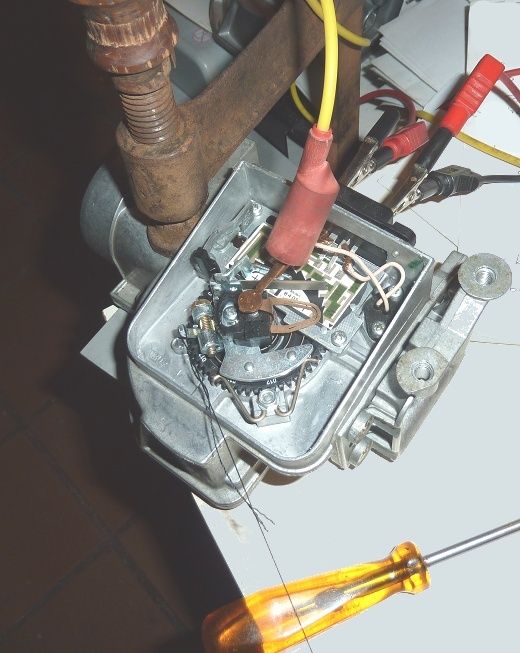
Figure 5. showing electrical connections, load attachment and clamping arrangement of the AFM under test.
A single G-clamp can be used to enable rotation of the unit as load increases to ensure that the radius from the axis to the point of attachment remains perpendicular to the line of tension in the thread. This needs to be adjusted about every four readings as the vane opens. Taking two readings at the same load, before and after movement of the unit, provides a check on how much error this is introducing. This can be seen as vertically superimposed points in the derived graphs. Care should be taken not crush the aluminium casting by exerting undue force with the clamp.
A known load can be applied using a measured amount of water ( eg. adding 2.5 ml at each step ). A recipient weighing less than the load needed to move the vane off the end stop should be used. This is about 50-55g at the lug on the back of the wiper assy. Water has a convenient density of 1.0 g/ml or 1 kg/litre ( 1.0 ml = 1.0 cc = 1.0 gram of water ). Graduated plastic syringes provide a useful way of applying a controlled amount of water to load the spring.
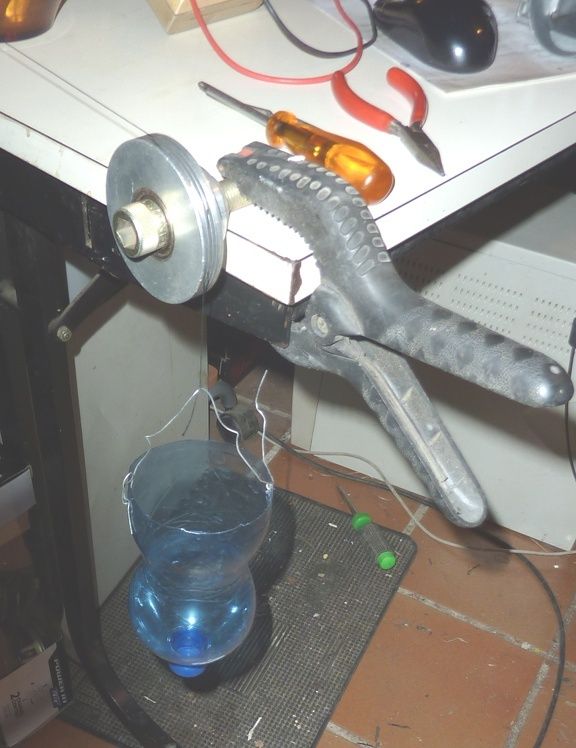
Figure 6. Applying a load using a measured quantity of water
A nice smooth pulley wheel should be used to minimise resistance so as not to bias the readings.
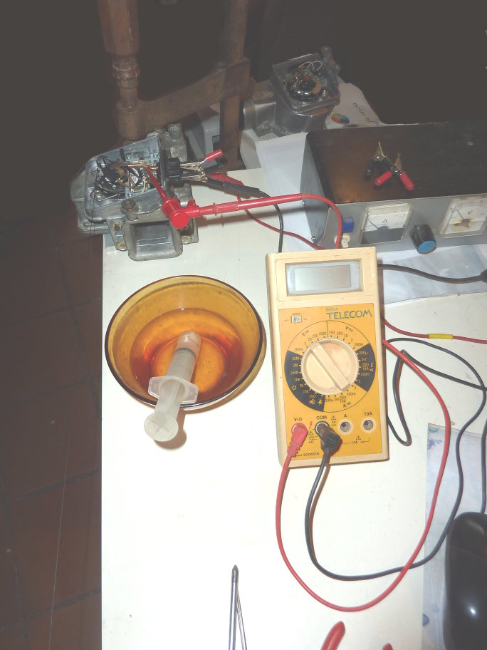
Figure 7. Bench power supply and voltmeter connections, with load attachment thread running near edge of bench.
Probe is clipped to central copper pickup arm, rather than pin7 itself. Pin 5 is the on the extreme left of the connector block, pin 8 on the right.
A stabilised bench power supply will have over-current protection in case of accidental shorts, which could cause damage. Otherwise a 6V motorcycle battery ( with fuse-holder ) could be used. It is imperative that the supply voltage remains stable throughout test. It should at least be checked at the start and end of the test run. In normal operation, 12V is applied to pin 9. The air temp. thermistor and other resistances between pin8 and pin9 drop the battery 12v to about 7.5V on pin 8 in real conditions. Anything around that value is suitable as a test voltage applied to pin 8, as long as it is constant.
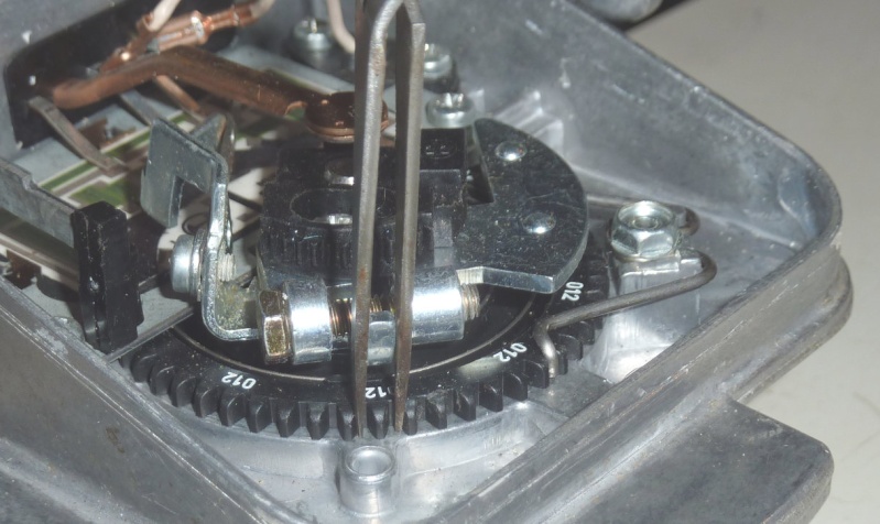
Figure 7b. Showing fine tweezers used as a guide to consistently align wiper plate lug with successive cog positions ( as used to produce figure 3.)
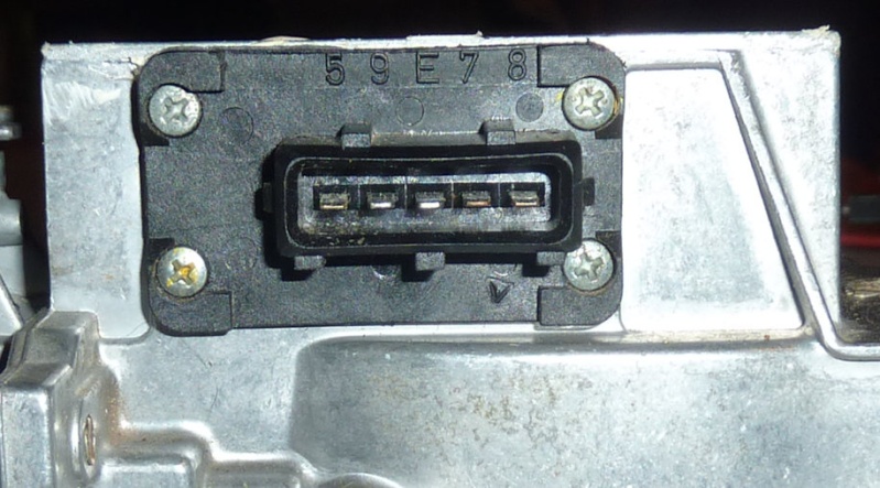
Figure 7c. Showing close up of AFM connector and pin numbers referred to in the article.
Visualising the test data:
Clearly it is very helpful to be able to visualise all these numbers and readings to see how the various calibrations affect the flowmeter. The graphs produced here have been done using some open source ( free ) software called Gnuplot. It is available for all major platforms http:www.gnuplot.info
Windows versions here: https://sourceforge.net/projects/gnuplot/files/gnuplot/5.0.3/ , Linux users will find it in their package management system. MacOS users here: http://www.flapane.com/nix.php
It reads in data from ordinary text files and takes commands typed into its command console. Pasting in the commands below should produce some similar to figure 3.
Gnuplot is a very powerful graphical tool once mastered and takes time to learn, but a few snippets of code will provide a means to reproduce what is presented here without the need for a tutorial on how to master the software. That codecan be reused to achieve a similar result if the same text file layout is used for the data file.
The following commands will recreate the voltage vs angular displacement graph in figure 3.
$0 refers to the line number in dataset, in this case the tooth number from starting position.
The following data stored in the file called "bosch_flowmeter.dat" were generated using the teeth on the spring tensioner wheel as an angular scale. A long, thin tweezer was used as a guide to ensure accurate alignment on each tooth. Here the load was not measured, simply the angular displacement from the rest position with the vane closed.
The torque test:
The torque test data was logged in two columns : col 1 the volume of added water, col 2 the voltage on pin7. The output was divided by the input voltage to give a normalised result maxing out at 1.0 , the weight of the water recipient ( 26 grams ) is added to column 1 and converted to a torque figure which is independent of the point of attachment. These calculations are done on the fly by the plotting commands.
The following code and data will produce figure 9 and can be adapted to produce similar graphs:
Test results:
To assess the effect of dead zone adjustment, the test unit wiper was set so that the output voltage moved off the set base value as soon as the vane was moved off the stop. This leads to earlier injection and a richening of the mixture compared to the unmodified unit with a notable dead zone.
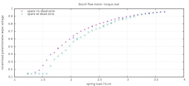
Figure 8 comparing a good, unmodified K75 ATM with a test unit with zero dead zone.
Road testing showed this zero setting was good but less than optimal. Some more experimentation resulted in a setting with a small dead zone that gave good results on the road, rapid snap open throttle response ( for a K ) and good low speed throttle control ( no marsupials ).
Subsequent tests on a gas analyser showed an AFR of 14.70 at tickover. Bang on the theoretical optimal mixture.
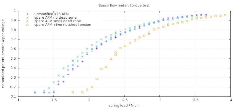
Fugire 9. Comparing the effect of adjusting the dead zone and spring pre-tension to that of a standard working AFM.
Resealing the casing:
To ensure the unit is protected from the potentially damp air in the air filter box where it is situated, it much be thoroughly resealed. The factory uses silicone sealant but many such pastes used for sealing casing use acetic acid ( white vinegar ) as a curing agent. This is know to be detrimental to electronic circuitry. It is not know whether this will affect the resistor network but in absence of such knowledge it would been best to avoid its use. There are electronics compatible silicone pastes available or a polyurethane mastic could be used. The latter is much stronger than silicone and should be used sparingly to avoid difficulty in future removal.
A thin bead of sealant should be applied to the recess around the plastic cover and wiped off to be a little lower than full. Similarly, if the contact plate was removed this should be refitted with sealant. To be really rigorous it may be good to flush the air in the potentiometer housing using a can of pressurised dry air which is available in electronics or computer shops. It would certainly be best to avoid sealing in warm summer air which holds considerable moisture. Cold morning air is preferable. Especially in tropical or semi-tropical regions dry air should be considered.
Conclusions:
Moving the resistor base plate provides a good way of getting a clean, new track whilst maintaining the factory contact pressure on the wiper contacts. This seems to be essential to ensure good contact and long service. The downside is the need ot reset the wiper rest position. The method developed here allows an objective measurement of the output of the AFM as a function of wiper zero position and thus a means of setting it up. It also reveals how the wiper rest position affects air fuel mixture accross the rev range and give some understanding of how adjusting it is affecting the AFR of the bike.
It is likely that there is some instrument drift in these units after 20y of service meaning the factory calibration may no longer be valid. The test procedure allows identification of whether an intervention is needed.
Taking a measurement of the output voltage vs the torque applied to the spring provides a thorough assessment of reliability of the unit under conditions which realistically represent in service usage. This will assess both electrical and mechanical defects that would lead to poor fuel regulation.
This text may get modiified as I spot errors or have them pointed out by others. I hope that this is useful to other brick-pilots. There seems to be a lack of reliable information and understanding of how these instruments work. Hopefully this will help fill that gap.
Appendix:
This circuit layout of the resistor chain maybe useful for reference:
http://www.k1100lt.de/files/flybrick/dkjk/luftmass/Seiten/Luftmassenmesser_2_gif.htm
From 'Dieters K Jetronik Kompendium'
The sum of all the resistors on the left is approximately 300 ohm, this means about half the battery voltage is exposed at pin8. Under normal service this is an input to the ECU which can then be compared to the potentiometer output on pin7, giving a ratio independent of fluctuations in the vehicle battery voltage.
The previous thread terminated here:
https://www.k100-forum.com/t10996p50-flowmeter-restoration#131627
Here I will try to condense it to a more coherent account.
Objective:
Determine whether the Bosch air flow meter ( AFM ) is defective; restore functionality; recalibrate rest position if moved during intervention or if recalibration is desired as a function of age, ie. find method to measure wiper position and re-adjust factory wiper calibration.
General description:
The Bosch AFM is based on a vane obstructing the air flow. The air flow into the inlet manifold pushes the vain against a return spring. Change in vane position displaces a potentiometer ( variable resistance ) and provides a voltage output, proportional to the volumetric air flow, to the ECU. This signal is used to control the volume of fuel injected by each fuel injector. A bypass screw controls the air flow through a bypass passage when the vane is closed under idle conditions.
There is also a thermistor ( temperature dependent resistor ) inserted into the air flow inlet. This acts as an air temperature sensor and forms part of the resistor chain that thus affects the output of the unit. This is a negative temperature coefficient device ( NTC ) whose resistance decreases with increasing temperature.
Construction detail:
The following image shows what it's all about: track wear due to years of a little cursor rubbing up and down each time the throttle is open or shut. How many million times has this moved in 20 odd years? I'm impressed with how long they last. This is a tribute to the rigorous design and top quality construction that german manufacturers are renown for. These are beautiful, precision instruments.
figure 1. Close up of track wear on Bosch AFM.
Though less clear in the photo, the dark lines on either side of wear mark tracks are a collection carbon power. This is easily blown off. This case of track wear is pretty typical of these units after 20y, not a case of extreme wear.
Note the usually sharp laser cuts in the green resistor blocks have gone fuzzy. This unit was badly stored. This is unusual degradation since on a K-bike they are well protected and usually look nearly new.
This is what the units look like inside. Comparison of early and later, factory modified, models are shown here:
https://www.k100-forum.com/t11043-bosch-air-flow-meter-version-differences
figure 2. General view of AFM internals.
There's loads of folklore out there about super accurate factory calibrations... don't evah touch this bit ... etc. The one thing that is factory precision calibrated at individual production item level is the value of the thick film resistors ( green rectangles ). These can not be mass produced to required accuracy and are individually laser trimmed to give a precise resistor chain providing a series of accurate voltage points along the black carbon strip where the copper wiper blade runs. This is the reference for the output. This calibration will not be lost by stripping and cleaning operations ( unless one is hamfisted and damages the unit ).
The preload of the multi-turn return spring is set to the nearest tooth during calibration. This is unlikely to require adjustment but should be marked if being removed. The preload, should it be lost is about 1.4 to 1.5 N.cm ; or 55 to 60 gram force applied at the lug behind the pinch bolt in the top left of the photo. It will be hard to start the motor if this is not very near the right position.
Because of the pre-load there is a certain amount of air which will pass through the bypass chamber when the vane is butted up against it's end stop in the closed, engine idle state. There is also typically a small movement of the vane possible before the output voltage changes. This is of the order of 1mm at the extremity of the vane. This movement will be referred to as dead zone in the following.
The ECU is totally analogue circuitry, not a micro-controller or 'computer' as many sources suggest. The circuit compares the output voltage of the AFM ( which is derived from the battery voltage ) with a fraction of the battery voltage. This gives it a degree of immunity from variations in the battery voltage. The inputs are buffered by integrated circuits ( operational amplifiers ) which draw minimal current. This means that resistance of the carbon track can be considerably higher than the low values of the lasers trimmed, fixed resistor chain, thus not affecting it. The carbon track just acts as in interpolation path between the set points of precision resistor chain. The resistance of the path is not critical since very little current is drawn. This is why testing the resistance of wiper contact externally is not an appropriate test. The contact pressure is intentionally very light to ensure longevity of carbon track. As a result the resistance can be very erratic.
Tests should be done with a voltage applied as under running conditions and the voltage at the wiper measured. Resistance measurements will not give a useful indication of the state of the AFM.
There are 12 resistors in the chain between pin 8 and pin 5 ( ground / chassis connection). Between pin 8 and pin 9 there are two more plus the thermistor temperature sensor. Battery voltage is applied at pin 9. This means that the thermistor modifies the resistor chain and thus the output, directly. This effectively applies a correction for changes in air density: it is the mass of air ( ie number of molecules ) which is relevant to the fuel requirement, not air volume.
The multi-turn return spring on the AFM provides a very linear ratio between angular deflection and applied torque. However, air flow through the flow meter varies approximately exponentially in relation to the vane deflection. For this reason, the resistor chain is arranged to have a logarithmic relation to position, the idea being that the output voltage will then be the log of the exponential: ie nearly a linear function of the volumetric air flow.
The following graph, using a logarithmic scale on x-axis shows that the output follows a log relationship over a wide range, then deviates somewhat towards fully opened positions. It is likely that gas flow is not truly exponential and this description is an over simplification. The unit will have been designed to return a good linear indicator of air mass flow.
Figure 3. Logarithmic plot of potentiometer output against angular deflection. Data show both an unmodified, used unit and a modified unit under test. Output voltage is normalised and given as a ratio of the input voltage.
The bottom line test for the flow meter is the output voltage measured as a function of the force applied to the vane return spring. A physical set up for applying a measured torque is described below. Figure 4 shows a suspect unit under test and a known functional unit. It is readily seen that this unit will give a very bad signal to the ECU and cause very poor injection regulation. However, it does progress in a roughly monotonic fashion and this rather serious default probably would not be obvious without systematic measurements.
Figure 4. AFM output as a function of torque on return spring. Unit under test shows very erratic behaviour.
Recovering a reliable output signal:
If the carbon track is worn to the point of producing erratic output as shown in figure 4., a clean track must be recovered. This implies moving the copper wiper arm in relation to the metal plate carrying the resistor network. There are two principal ways to achieve this: a) move the track; b) move / bend the wiper arm.
Several sources suggest bending ( kinking ) the wiper arm to shorten it in order to find a new track. Others suggest raising or lowering the wiper arm height where it is clamped to the spindle. The major disadvantage of both these methods is that there is no control over the contact pressure of the wiper contacts on the carbon track. This will necessarily mean they end up with too much or too little pressure. It can be assumed that Bosch studied this quite closely in order to design the maximum lifetime whilst ensuring proper reliable electrical contact. Any ad hoc messing around with this arm will either be unreliable or lead to accelerated wear of the new track. Rather counter productive outcomes.
Option a) allows retaining the designed pressure by not distorting the wiper arm. The inconvenience is that it will disturb the calibration of the output in relation to the vane position. This can have a notable affect on mixture across the full range and needs to be correctly reset afterwards.
Moving the resistor plate.
Before removing the plate, it would be desirable to set up the recalibration procedure below and get a good calibration curve as a reference. This will save a lot of testing and tuning later. Also a score to mark the position of black plastic base of the wiper arm before removing the spot of thermal glue locking the retaining screw. Once that is removed you are committed to spending some time recalibrating its position.
Also note the height of the wiper mechanism on the 1/4" spindle. Usually the end of the spindle will be flush with top of the black plastic heel of the wiper. This should go back in the correct position to retain the correct contact pressure on the wiper arm. This is important. The resistor plate can be removed with this in place but it does risk bending the wiper. It is safest to remove the whole wiper assembly by slackening the pinch bolt at the back. The plate may still nip onto the shaft and need easing off.
Remove the electrical connector block from the casting, then the wiper assy, then the resistor plate.
The resistors network is set on a ceramic substrate bonded to a solid metal plate. This plate is attached to the AFM body by three screws. This plate can be removed by first removing the electrical connector plate entering the AFM. This is retained by four screws and is also sealed with silicone. The mounting holes in the metal plate can be slightly elongated to allow positioning the plate closer to the body of the AFM by moving it slightly towards the connector plug. 0.5 to 1.0 mm is enough to get a clean track of virgin material.
Care needs to be taken not to damage the carbon film resistors or the carbon track while working on the holes. Both are rather fragile to knocks and scratched. Extreme caution is needed.
Once the plate is back in place and locked into a position giving a clean track for the wiper, it is necessary to reset the starting position of the wiper in relation to the resistor network. This can be initially done by aligning the contact points radially with the corner of the first green rectangular resistor. It will already be close. This should be close enough to start the engine, though unlikely to run well. The limit of the old wiper wear marks on the carbon track will be a guide.
Calibration test procedure:
The basic method is to progessively apply a known force to a radial point on the wiper assembly and measure the voltage at the wiper connector ( pin 7 ) whilst applying a fix voltage ( 6.0V) on pin 8. This bypasses the variable thermistor air temperature sensor which should be excluded from this test. Pin5 is ground.
Figure 5. showing electrical connections, load attachment and clamping arrangement of the AFM under test.
A single G-clamp can be used to enable rotation of the unit as load increases to ensure that the radius from the axis to the point of attachment remains perpendicular to the line of tension in the thread. This needs to be adjusted about every four readings as the vane opens. Taking two readings at the same load, before and after movement of the unit, provides a check on how much error this is introducing. This can be seen as vertically superimposed points in the derived graphs. Care should be taken not crush the aluminium casting by exerting undue force with the clamp.
A known load can be applied using a measured amount of water ( eg. adding 2.5 ml at each step ). A recipient weighing less than the load needed to move the vane off the end stop should be used. This is about 50-55g at the lug on the back of the wiper assy. Water has a convenient density of 1.0 g/ml or 1 kg/litre ( 1.0 ml = 1.0 cc = 1.0 gram of water ). Graduated plastic syringes provide a useful way of applying a controlled amount of water to load the spring.
Figure 6. Applying a load using a measured quantity of water
A nice smooth pulley wheel should be used to minimise resistance so as not to bias the readings.
Figure 7. Bench power supply and voltmeter connections, with load attachment thread running near edge of bench.
Probe is clipped to central copper pickup arm, rather than pin7 itself. Pin 5 is the on the extreme left of the connector block, pin 8 on the right.
A stabilised bench power supply will have over-current protection in case of accidental shorts, which could cause damage. Otherwise a 6V motorcycle battery ( with fuse-holder ) could be used. It is imperative that the supply voltage remains stable throughout test. It should at least be checked at the start and end of the test run. In normal operation, 12V is applied to pin 9. The air temp. thermistor and other resistances between pin8 and pin9 drop the battery 12v to about 7.5V on pin 8 in real conditions. Anything around that value is suitable as a test voltage applied to pin 8, as long as it is constant.

Figure 7b. Showing fine tweezers used as a guide to consistently align wiper plate lug with successive cog positions ( as used to produce figure 3.)
Figure 7c. Showing close up of AFM connector and pin numbers referred to in the article.
Visualising the test data:
Clearly it is very helpful to be able to visualise all these numbers and readings to see how the various calibrations affect the flowmeter. The graphs produced here have been done using some open source ( free ) software called Gnuplot. It is available for all major platforms http:www.gnuplot.info
Windows versions here: https://sourceforge.net/projects/gnuplot/files/gnuplot/5.0.3/ , Linux users will find it in their package management system. MacOS users here: http://www.flapane.com/nix.php
It reads in data from ordinary text files and takes commands typed into its command console. Pasting in the commands below should produce some similar to figure 3.
Gnuplot is a very powerful graphical tool once mastered and takes time to learn, but a few snippets of code will provide a means to reproduce what is presented here without the need for a tutorial on how to master the software. That codecan be reused to achieve a similar result if the same text file layout is used for the data file.
The following commands will recreate the voltage vs angular displacement graph in figure 3.
$0 refers to the line number in dataset, in this case the tooth number from starting position.
- Code:
set title "Bosch flow meter: angular displacement test"
set xlab "spring tensioner wheel tooth number ( closed = 1 )"
set ylab "potentiometer wiper voltage"
set key top left Left reverse
vref=5.98

 plot "bosch_flowmeter.dat" using ($0):($1/vref) index 0 w p tit "modified unit", "" using ($0):(($1/vref)) index 1 w p tit "untampered unit"
The following data stored in the file called "bosch_flowmeter.dat" were generated using the teeth on the spring tensioner wheel as an angular scale. A long, thin tweezer was used as a guide to ensure accurate alignment on each tooth. Here the load was not measured, simply the angular displacement from the rest position with the vane closed.
- Code:
# first data is K100 hacked unit : suspect spring has been moved from factory setting.

# index 0:  K100 tampered unit , using alignment guide
0.85
2.18
3.10
3.87
4.34
4.70
4.96
5.22
5.29
5.39
5.54
5.64
5.73
5.78
5.83
5.87
# two blank lines must separate data runs, re. "index" in the plotting command.


# index 1:  good K75 unit, using alignment guide
0.86
1.81
2.96
3.73
4.23
4.59
4.84
5.14
5.36
5.53
5.64
5.73
5.79
5.83
5.86
The torque test:
The torque test data was logged in two columns : col 1 the volume of added water, col 2 the voltage on pin7. The output was divided by the input voltage to give a normalised result maxing out at 1.0 , the weight of the water recipient ( 26 grams ) is added to column 1 and converted to a torque figure which is independent of the point of attachment. These calculations are done on the fly by the plotting commands.
The following code and data will produce figure 9 and can be adapted to produce similar graphs:
- Code:
set title "Bosch flow meter: torque test"
set xlab "spring load / N.cm "
set ylab "noramlised potentiometer wiper voltage"
set key top left Left reverse
vref=6.01
rad= 27.4e-3; g=9.81


plot "torque_test.dat" using (($1+26)*g*rad/10.):($2/vref) index 1  title "unmodified K75 AFM" \
, "" using (($1+26)*g*rad)/10.:($2/vref) index 2 title "spare AFM no dead zone" \
, "" using (($1+26)*g*rad)/10.:($2/vref) index 3 title "spare AFM small dead zone"\
, "" using (($1+26)*g*rad)/10.:($2/vref) index 0 title "spare AFM +two notches tension"
- click to see data for figure 9:
- Code:
# test after adding 2 notches to spring tension and realigning wiper closed posn.
# V ref = 5.98
# lift off @40g
# index 0

40.0 .865
45.0 .865
47.5 1.05
50.0 1.213
52.5 1.72
55.0 2.35
57.5 2.46
60.0 2.96
62.5 3.22
62.5 3.36 #
65.0 3.64
67.5 3.78
70.0 3.95
72.5 4.12
75.0 4.30
77.5 4.39
80.0 4.51
80.0 4.60 #R
82.5 4.81
85.0 4.88
87.5 4.97
90.0 5.07
90.0 5.11 #R
92.5 5.15
95.0 5.19
97.5 5.25
100.0 5.31
102.7
102.5 5.44
105.0 5.49
107.5 5.53
110.0 5.567
112.5 5.60
115.0 5.65
117.5 5.67
120.0 5.69
 # vref end 5.96


# good spare unit. +0 notch. re-aligned wiper
# V ref = 5.99
# lift off @20g water
# index 1

20.0 .867
25.0 .867
30.0 .867
32.5 1.36
35.0 1.54
37.5 1.99
40.0 2.28
40.0 2.35
42.5 2.50
45.0 2.80
47.5 3.24
50.0 3.44
52.5 3.60
52.5 3.64 #R
55.0 3.85
57.5 4.07
60.0 4.16
62.5 4.31
62.5 4.30
65.0 4.48
67.5 4.60
70.0 4.72
72.5 4.82
75.0 4.89
75.0 4.97 #R
77.5 5.03
80.0 5.13
82.5 5.23
85.0 5.29
87.5 5.39
87.5 5.46
90.0 5.52
92.5 5.53
95.0 5.57
97.5 5.58
100.0 5.62
100.0 5.65 #R
102.5 5.68
105.0 5.69
107.5 5.73
110.0 5.73
 # vref end 5.98


# good spare back to +0 ; reset to  no dead zone
# index 2
# lift off 25g
# vref=5.98

20.0 0.87
25.0 0.97
27.5 1.12
30.0 1.50
32.5 1.92
35.0 2.36
37.5 2.51
40.0 2.82
40.0 2.87
42.5 3.09
45.0 3.34
47.5 3.56
#100 3.67
50.0 3.83 #R
52.5 4.01
55.0 4.18
57.5 4.33
60.0 4.45
62.5 4.54
62.5 4.60 #R
65.0 4.68
67.5 4.80
70.0 4.88
72.5 4.96
72.5 4.96 #R
75.0 5.06
77.5 5.13
80.0 5.23
80.0 5.23 #R
82.5 5.25
85.0 5.33
87.5 5.37
90.0 5.44
92.5 5.48
95.0 5.53
97.5 5.59
100.0 5.60
100.0 5.61
102.5 5.64
105.0 5.66
107.5 5.70
110.0 5.72
# vref 5.95


# spare , re-introduce sm dead zone
# vref=5.98
# index 3
# lift off 27.5g

20.0 0.86
25.0 0.86
27.5 0.86
30.0 0.94
32.5 1.55
35.0 1.85
37.5 2.28
40.0 2.57
40.0 2.57 #R
42.5 2.82
45.0 3.11
47.5 3.35
50.0 3.57
50.0 3.58 #R
52.5 3.76
55.0 3.92
57.5 4.07
60.0 4.27
60.0 4.28 #R
62.5 4.39
65.0 4.52
67.5 4.65
70.0 4.72
70.0 4.75 #R
72.5 4.82
75.0 4.91
77.5 5.05
80.0 5.11
80.0 5.14
82.5 5.22
85.0 5.30
85.0 5.32 #R
87.5 5.38
90.0 5.42
92.5 5.46
95.0 5.52
95.0 5.54 #R
97.5 5.56
100.0 5.61
102.5 5.65
105.0 5.68
107.5 5.70
110.0 5.72
# vref =5.98
Test results:
To assess the effect of dead zone adjustment, the test unit wiper was set so that the output voltage moved off the set base value as soon as the vane was moved off the stop. This leads to earlier injection and a richening of the mixture compared to the unmodified unit with a notable dead zone.
Figure 8 comparing a good, unmodified K75 ATM with a test unit with zero dead zone.
Road testing showed this zero setting was good but less than optimal. Some more experimentation resulted in a setting with a small dead zone that gave good results on the road, rapid snap open throttle response ( for a K ) and good low speed throttle control ( no marsupials ).
Subsequent tests on a gas analyser showed an AFR of 14.70 at tickover. Bang on the theoretical optimal mixture.
Fugire 9. Comparing the effect of adjusting the dead zone and spring pre-tension to that of a standard working AFM.
Resealing the casing:
To ensure the unit is protected from the potentially damp air in the air filter box where it is situated, it much be thoroughly resealed. The factory uses silicone sealant but many such pastes used for sealing casing use acetic acid ( white vinegar ) as a curing agent. This is know to be detrimental to electronic circuitry. It is not know whether this will affect the resistor network but in absence of such knowledge it would been best to avoid its use. There are electronics compatible silicone pastes available or a polyurethane mastic could be used. The latter is much stronger than silicone and should be used sparingly to avoid difficulty in future removal.
A thin bead of sealant should be applied to the recess around the plastic cover and wiped off to be a little lower than full. Similarly, if the contact plate was removed this should be refitted with sealant. To be really rigorous it may be good to flush the air in the potentiometer housing using a can of pressurised dry air which is available in electronics or computer shops. It would certainly be best to avoid sealing in warm summer air which holds considerable moisture. Cold morning air is preferable. Especially in tropical or semi-tropical regions dry air should be considered.
Conclusions:
Moving the resistor base plate provides a good way of getting a clean, new track whilst maintaining the factory contact pressure on the wiper contacts. This seems to be essential to ensure good contact and long service. The downside is the need ot reset the wiper rest position. The method developed here allows an objective measurement of the output of the AFM as a function of wiper zero position and thus a means of setting it up. It also reveals how the wiper rest position affects air fuel mixture accross the rev range and give some understanding of how adjusting it is affecting the AFR of the bike.
It is likely that there is some instrument drift in these units after 20y of service meaning the factory calibration may no longer be valid. The test procedure allows identification of whether an intervention is needed.
Taking a measurement of the output voltage vs the torque applied to the spring provides a thorough assessment of reliability of the unit under conditions which realistically represent in service usage. This will assess both electrical and mechanical defects that would lead to poor fuel regulation.
This text may get modiified as I spot errors or have them pointed out by others. I hope that this is useful to other brick-pilots. There seems to be a lack of reliable information and understanding of how these instruments work. Hopefully this will help fill that gap.
Appendix:
This circuit layout of the resistor chain maybe useful for reference:
http://www.k1100lt.de/files/flybrick/dkjk/luftmass/Seiten/Luftmassenmesser_2_gif.htm
From 'Dieters K Jetronik Kompendium'
The sum of all the resistors on the left is approximately 300 ohm, this means about half the battery voltage is exposed at pin8. Under normal service this is an input to the ECU which can then be compared to the potentiometer output on pin7, giving a ratio independent of fluctuations in the vehicle battery voltage.
Last edited by Beamer on Thu Sep 17, 2020 10:32 am; edited 21 times in total