BMW K bikes (Bricks)


You are not connected. Please login or register

View previous topic View next topic Go down  Message [Page 1 of 1]


1Back to top Go down   Speedo defecit Empty Speedo defecit Sun Nov 13, 2011 2:44 pm

BooG

BooG
Platinum member
Platinum member
Speedo on My K75S shows 5mph to slow at mo. Have been reading the relevant topics, and here are some questions..
1/ My speedo is in MPH and KARAMBA is in KPH.....can I still use it?
2/ Karamba only shows up the discrepancy: I still have to access the potentiometer to adjust?
3/ Assuming I can use Karamba(?), what wire corresponds to 18GA re the cables that plug into the loom?
4/ A straightforward cleaning up of the possibly corroded connections in the speedo will fix the problem?
5/ I have some moisture in the speedo...what is the best way to eradicate it from the speedo?
Thanks in advance.


2Back to top Go down   Speedo defecit Empty Re: Speedo defecit Sun Nov 13, 2011 4:42 pm

BooG

BooG
Platinum member
Platinum member
Also....why do some people suggest using copper/Aluminium based anti seize to refit connectors at the rear of the instrument pod, whilst others say you should not use metallic based anti seize? I thought a silicon based dielectric grease would be just the thing...no?


3Back to top Go down   Speedo defecit Empty Re: Speedo defecit Sun Nov 13, 2011 7:45 pm

Rick G

Rick G
admin
admin
BooG wrote:Speedo on My K75S shows 5mph to slow at mo. Have been reading the relevant topics, and here are some questions..
1/ My speedo is in MPH and KARAMBA is in KPH.....can I still use it? Yes, you just need to convert it mentaly
2/ Karamba only shows up the discrepancy: I still have to access the potentiometer to adjust? Correct
3/ Assuming I can use Karamba(?), what wire corresponds to 18GA re the cables that plug into the loom? Best to plug into the sensor cable under the right side cover
4/ A straightforward cleaning up of the possibly corroded connections in the speedo will fix the problem? No but it is a good idea to clean them with DeoxIT it certainly help
5/ I have some moisture in the speedo...what is the best way to eradicate it from the speedo? The early Ks had quite a problem with moisture. BMW placed gortex breathers in the base plate of the instruments on the later models.
Thanks in advance.
My answers are in Red

There are quite a few write ups on keeping the water out, if you use the search you will find them. They mainly are for putting gortex breathers in the early cases
To convert Miles to Kilometres multiply by 1.6,
Access to the pot is by dismantling the unit and the trim pot is under the speedo http://www.ibmwr.org/ktech/speedo-adjust2.jpg
These are the pin allocation on the back of the speedo those in red are the ones you can use for a bench run, I am not sure which brown earth wire is relevant so connect both
1 - Red/White - Clock Power (other stuff too)
2 - Yellow/White - Gear Position Switch
3 - Yellow/Black - Gear Position Switch
4 - Yellow/Blue - Gear Position Switch
5 - Black/Green - Starter Switch(12V if 2, 3 &4 are grounded - gear=0)
6 - Green/Black - Power
7 - White - Low fuel lamp
8 - Green/Yellow - ABS Warning Relay
9 - Blue - Alternator
10 - Violet/black - Temp relay
11 - Brown/Green - Oil light
12 - Violet/White - Choke indicator
13 - Brown - Ground
14 - White/Blue - Bulb monitor
15 - White - High beam
16 - Black/Blue - Tachometer
17 - Blue/Black - Right turn indicator
18 - Brown - Ground
19 - Blue/Red - Left turn indicator
20 - -
21 - Blue/Green - Turn signal cancel on flasher relay
22 - Yellow - Speed Sensor
23 - Brown - Ground
24 - Gray/Blue - Backlights


This will keep you busy for a day or two.


__________________________________________________
"Man sacrifices his health in order to make money.
Then he sacrifices money to recuperate his health.
And then he is so anxious about the future that he does not enjoy the present; the result being that he does not live in the present or the future; he lives as if he is never going to die, and then dies having never really lived."   Dalai Lama


Bikes 1999 K1100 LT with a Big Block 1200
    

4Back to top Go down   Speedo defecit Empty Re: Speedo defecit Sun Nov 13, 2011 8:35 pm

robmack

robmack
Life time member
Life time member
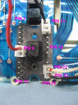
K Freak wrote:These are the pin allocation on the back of the speedo those in red are the ones you can use for a bench run, I am not sure which brown earth wire is relevant so connect both
Use pin 13 for the speedo testing and calibration. The other ground is for lighting.

Here is additional text that I added to my Karamba User's Guide (but haven't uploaded yet; too busy with work and a three year old tornado, A.K.A. my son.

Cable Hookup
To bench test, the instrument cluster must be supplied +12 volt DC from an external source such as a battery or power supply. In addition, provision must be made to hook up proper signals to the transducer inputs on the cluster.
The power supply cable is very simple. I used alligator clips attached to wires that terminated in 2-terminal Molex header connectors with 0.156” pins. This particular header connector has the correct pin spacing for the instrument cluster. The reason I used 2-terminal Molex connectors instead of 1-terminal was to ensure that the connections were oriented properly. Crimp Molex terminals on one end of the wire and insert into one of the shell’s holes (doesn’t matter which one). Solder an alligator clip onto the other end of the wire. Repeat for a second wire.
Similarly, manufacture a signal cable using the instructions provided earlier in this document however, instead of using ¼” spade connectors, use a 2-terminal Molex connector.
1. Connect the power and signal cables to the main header connector back of the instrument cluster in the following way:
• +12VDC is connected to Pin 6
• Power ground is connected to Pin 13
• Signal+ is connected to Pin 22
• Signal- is connected to Pin 23
You can see the proper connections in the photo
Speedo defecit Speedo%252520connection
2. Connect the 3.5mm stereo plug to the laptop. Connect +12V to the positive of a power source; connect Ground to the negative of a power source
3. Run the Karamba program.
Hint
Normally, one disconnects the speedometer subassembly to provide maximum access to the adjustment potentiometer. I have found that it is possible to orient the speedometer subassembly without disconnecting it in order to adjust the potentiometer while the Karamba program is running. This greatly speeds the process of adjusting the speedometer’s precision. Remove the speedometer sub-assembly from the instrument cluster as described above. Reconnect the 4-pin header and flexible circuit card that attached the speedometer sub-assembly to the main circuitry. Be careful not to kink or stretch the flexible circuit card as it could damage the copper traces. The only caution to take is to be careful when inserting the jeweler’s screwdriver into the innards of the speedometer sub-assembly to make sure you don’t accidently short out electronics. You can adjust the pot and watch its response on the display realtime. The process of converging the speedometer’s reading is reduced to just a few seconds because you get instant feedback how your adjustment is affecting the needle.

Speedo defecit Bench%252520test%252520layout

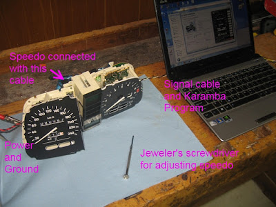
The image above shows the orientation of the speedo that just offers enough room to access the adjustment pot while still allowing the flexi-cables to be connected yet not stressing them.


__________________________________________________
Robert
1987 K75 @k75retro.blogspot.ca
http://k75retro.blogspot.ca/
    

5Back to top Go down   Speedo defecit Empty Re: Speedo defecit Sun Nov 13, 2011 8:59 pm

robmack

robmack
Life time member
Life time member
BooG wrote:Also....why do some people suggest using copper/Aluminium based anti seize to refit connectors at the rear of the instrument pod, whilst others say you should not use metallic based anti seize? I thought a silicon based dielectric grease would be just the thing...no?
Neither is appropriate. The Deoxit suggested by Kfreak has two primary components -- a cleaner for removing oxidation from contacts and a protectant to ensure long term protection of the contact so that oxygen is not able to get at the connection and oxidize it again. This special-purpose product works better and lasts longer than the two you have suggested.


__________________________________________________
Robert
1987 K75 @k75retro.blogspot.ca
http://k75retro.blogspot.ca/
    

6Back to top Go down   Speedo defecit Empty Re: Speedo defecit Sun Nov 13, 2011 10:40 pm

blaKey

avatar
Life time member
Life time member
As previously mentioned by K Freak and robmack, dielectric grease is a nonconductive grease. As such, it does not enhance the flow of electrical current, whereas DeoxIT cleans, restores and enhances electrical flow.


__________________________________________________
Neil
K100RS 1986 RED!

Dress for the ride and the potential slide.
    

7Back to top Go down   Speedo defecit Empty Re: Speedo defecit Mon Nov 14, 2011 4:54 am

BooG

BooG
Platinum member
Platinum member
Tremendous info!! Thanks alot!


8Back to top Go down   Speedo defecit Empty Re: Speedo defecit Mon Nov 14, 2011 5:44 am

Ghost who rides

Ghost who rides
Life time member
Life time member
I did my cluster some years ago when DeoxIT was not etched into my brain as it now is . Both speedo and tacho came good but speedo fix was fairly short lived.
At the time i was following the advice of of the BMWOA site ie twisting pins etc .
Today i spoke to an independent BMW repair business chap who says that the problem is the contact between the copper wire and the pin , dissimilar metals, and soldering is the answer ! This rings true to me 'cos my pins were bright and shiny, certainly no corrosion.
Comments on this please.
Gordon


__________________________________________________
1986  K 75 C   2nd owner 187,000kms showing .
1987  K100RT  Police repainted, rough and unloved.
    

9Back to top Go down   Speedo defecit Empty Re: Speedo defecit Mon Nov 14, 2011 7:29 am

mike d

avatar
Life time member
Life time member
Robmack wrote
The only caution to take is to be careful when inserting the jeweler’s screwdriver into the innards of the speedometer sub-assembly to make sure you don’t accidently short out electronics.

Why not use a non conductive pot trimmer, this will eliminate the risk of a short circuit?

Mike


10Back to top Go down   Speedo defecit Empty Re: Speedo defecit Mon Nov 14, 2011 8:13 am

robmack

robmack
Life time member
Life time member
mike d wrote:Why not use a non conductive pot trimmer, this will eliminate the risk of a short circuit?
Yes, Mike. That's certainly an option though most mechanics would not have one; electronic enthusiasts might. Most all have jeweler's screwdrivers. I thought afterwards that wrapping the shaft of the screwdriver with scotch tape would insulate it enough to reduce the risk.


__________________________________________________
Robert
1987 K75 @k75retro.blogspot.ca
http://k75retro.blogspot.ca/
    

11Back to top Go down   Speedo defecit Empty Re: Speedo defecit Mon Nov 14, 2011 8:37 am

mike d

avatar
Life time member
Life time member
Robmack wrote Yes, Mike. That's certainly an option though most mechanics would not have one; electronic enthusiasts might. Most all have jeweler's screwdrivers. I thought afterwards that wrapping the shaft of the screwdriver with scotch tape would insulate it enough to reduce the risk.

True enough - I've got some none metallic ones from my days in telecoms.

You could even use some small diameter heat shrink sleeving to insulate the shaft, but I'm probably being a bit OTT Rolling Eyes

Mike


12Back to top Go down   Speedo defecit Empty Re: Speedo defecit Mon Nov 14, 2011 1:32 pm

Inge K.

Inge K.
VIP
VIP
Ghost who rides wrote: Today i spoke to an independent BMW repair business chap who says that the problem is the contact between the copper wire and the pin , dissimilar metals, and soldering is the answer ! This rings true to me 'cos my pins were bright and shiny, certainly no corrosion.
Comments on this please.
Gordon
I can confirm that this is a problem, and did write a few words about it in the end of this thread.

It also can be mentioned that after I did write in that thread, this problem also have occured at the
bottom of the speedometer pin on my oldest one, which have been soldered between the pin and the
conductive film.

Sometimes soldering at these spots can be difficult due to the thight space, and/or to much of the
material on the conductive film have been lost because of corrosion.
When these circumstances have occured I`ve soldered a thin wire (0,2 mm2) between the
actual pin and connection point at the opposite end, and bypassed the conductive film.

Inge K.


13Back to top Go down   Speedo defecit Empty Re: Speedo defecit Tue Nov 15, 2011 12:55 am

K-BIKE

avatar
Life time member
Life time member
On this site search is your friend there has been a lot said on this subject including the following I wrote a while back http://k100rt.aforumfree.com/t223-led-lights-in-the-instrument-pod-plus-sealing-out-the-moisture?highlight=sealing+instrument
Regards,
K-BIKE


Sponsored content


View previous topic View next topic Back to top  Message [Page 1 of 1]

Permissions in this forum:
You cannot reply to topics in this forum