BMW K bikes (Bricks)


You are not connected. Please login or register

View previous topic View next topic Go down  Message [Page 1 of 1]


jhouse07

jhouse07
active member
active member
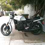
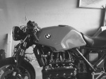
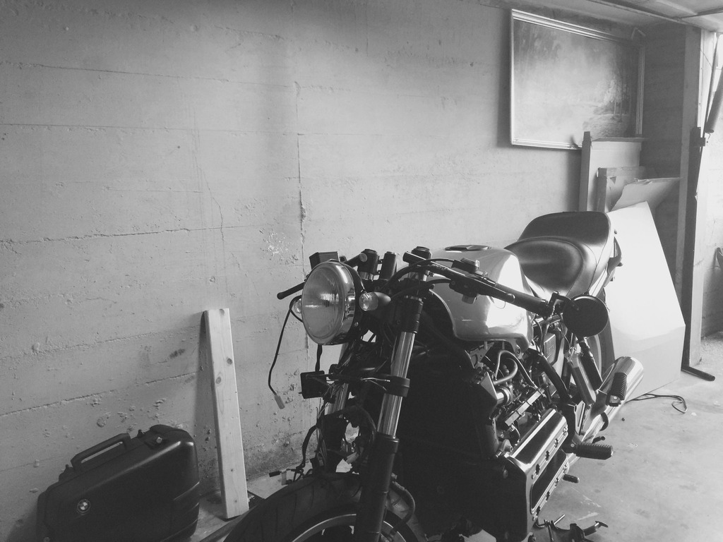
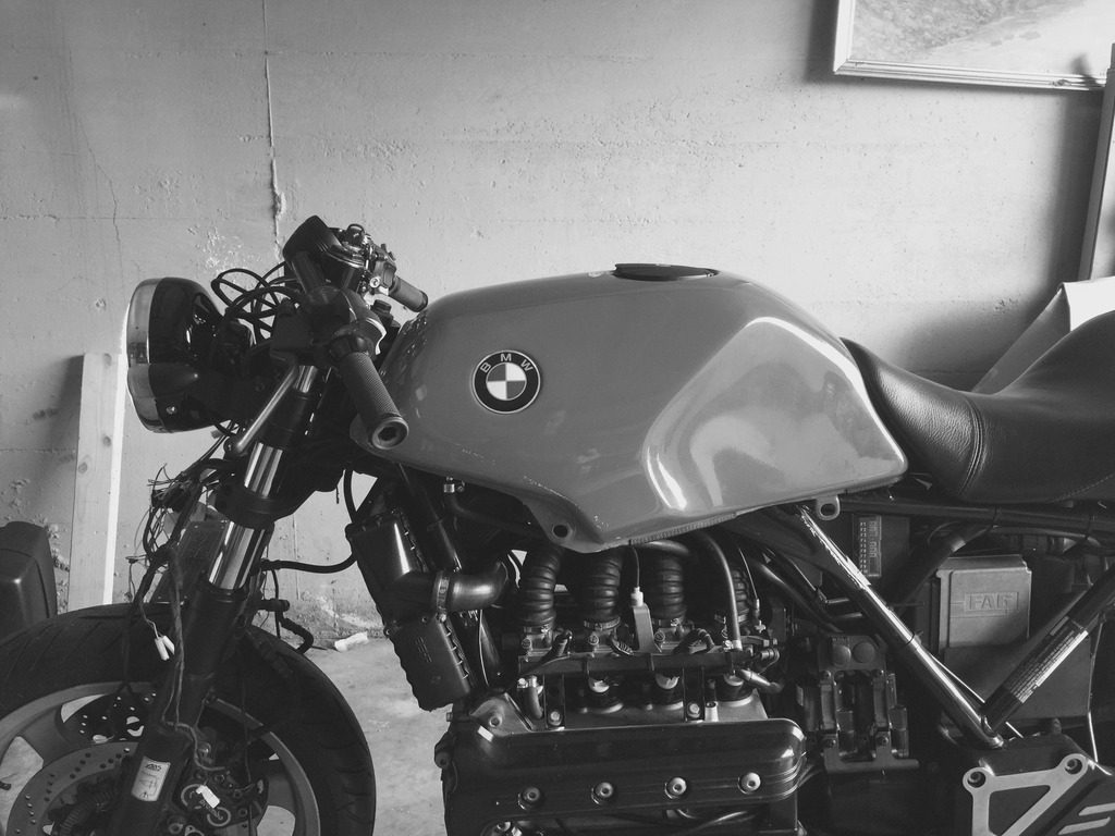
Began working on my 96 k1100rs and ran into some issues after following this great thread. https://www.k100-forum.com/t2611-my-k100-cafe-racer-project-story

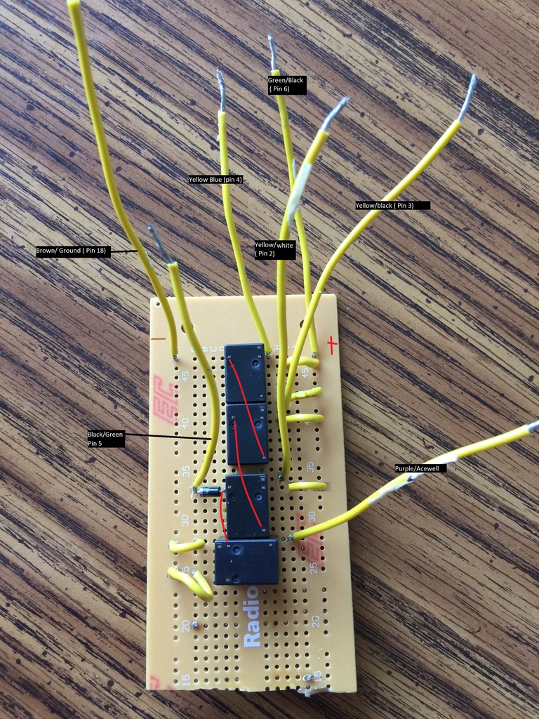
My acewell 2853 is still showing the neutral light always on and bike can only be started holding the clutch. I created a circuit board as noted in the thread above but it seems to not make any difference. Still hearing a clicking from a relay on the bike when the ignition is turned also. 


Still trouble with speedometer after much work IMG_2567

Still trouble with speedometer after much work IMG_2570


2Back to top Go down   Still trouble with speedometer after much work Empty multimeter testing Sat Mar 28, 2015 12:34 am

jhouse07

jhouse07
active member
active member
after further thought. i am going to check this circuit with a multimeter and post back


kringb

kringb
Silver member
Silver member
Nice looking bike. 

If your still having trouble after checking with a meter, what kind of relays are you using?

I had also followed that same thread when hooking up my acewell. I enlarged the photo of the relays that the OP used and bought those but could not get them to work. It turns out those are rated for an AC load circuit. There is also a diode needed that is not mentioned in that thread. 

Here is the thread that I had with the clever members who helped me figure it out. How to wire an Acewell


Last edited by kringb on Sat Mar 28, 2015 1:34 am; edited 1 time in total (Reason for editing : Spelling)


__________________________________________________
85 k100rs | 78 xs650
    

jhouse07

jhouse07
active member
active member
kringb wrote:Nice looking bike. 

If your still having trouble after checking with a meter, what kind of relays are you using?

I had also followed that same thread when hooking up my acewell. I enlarged the photo of the relays that the OP used and bought those but could not get them to work. It turns out those are rated for an AC load circuit. There is also a diode needed that is not mentioned in that thread. 

Here is the thread that I had with the clever members who helped me figure it out. How to wire an Acewell


Thanks

I have studied both, But will re venture. 

I used four small 12v relays ( ouaz-ss-112d) and a 1amp diode ( 1n4004) I used the schematic posted below. 

Still trouble with speedometer after much work IMG_2535


robmack

robmack
Life time member
Life time member
The original circuit in that thread you referenced is missing the diode to the start enable circuit. Compare it to this circuit below:

http://classickbikes.com/ckb.tech/0.ckb.tech.files/gpiemulate/gpiemulate.htm

Adding a 1N4001 diode will solve the problem. The relays can be any SPST with 12 volt DC coil. Contacts rated for AC will not impede the function.


__________________________________________________
Robert
1987 K75 @k75retro.blogspot.ca
http://k75retro.blogspot.ca/
    

Inge K.

Inge K.
VIP
VIP
As the neutral lamp stays on at all time and the start button gets power only
only when the clutch lever is pulled, it must be more than one thing that went
wrong during connecting the relays.


A guess is that the wire between the fourth relay and the neutral LED in the
Acewell is shorted to ground.

About the need to pull the clutch.....could be that the diode is wrong mounted,
the ring on the diode should point away from the relays.
It could be that you have a bad diode that don't let power through in either
direction.....this did happen to another member here a couple of years back.


__________________________________________________
Inge K.
K100RS -86. (first owner), K1100LTSE -94.
    

jhouse07

jhouse07
active member
active member
Inge K. wrote:As the neutral lamp stays on at all time and the start button gets power only
only when the clutch lever is pulled, it must be more than one thing that went
wrong during connecting the relays.


A guess is that the wire between the fourth relay and the neutral LED in the
Acewell is shorted to ground.

About the need to pull the clutch.....could be that the diode is wrong mounted,
the ring on the diode should point away from the relays.
It could be that you have a bad diode that don't let power through in either
direction.....this did happen to another member here a couple of years back.

Here is some photos of my board and also a video of what it looks like currently. Thanks for the advice everyone. 

Still trouble with speedometer after much work IMG_2581Still trouble with speedometer after much work IMG_2580


Inge K.

Inge K.
VIP
VIP
Have some problems to judge what is connected to what in the pictures
of the boards.

The relay that is clicking is the ABS warning lamp relay.


__________________________________________________
Inge K.
K100RS -86. (first owner), K1100LTSE -94.
    

jhouse07

jhouse07
active member
active member
Here is a layout. Still no sound from the relays also. 

Still trouble with speedometer after much work IMG_2580_1


Inge K.

Inge K.
VIP
VIP
Like it looks on the picture.....it should have functioned.

And you're shure that you have used the NO (87) contact and not the
NC (87a) contact on the relays?


__________________________________________________
Inge K.
K100RS -86. (first owner), K1100LTSE -94.
    

jhouse07

jhouse07
active member
active member
Inge K. wrote:Like it looks on the picture.....it should have functioned.

And you're shure that you have used the NO (87) contact and not the
NC (87a) contact on the relays?

I clipped the 87a on all the relays. One thing that is different on my 1996 k1100rs is that the Green/Black pin 6 is actually just green. So that was the only major different i found between. I am thinking it is the same thing. I picked up a multi meter and am curious how i can use it to test it out.


Inge K.

Inge K.
VIP
VIP
Select ohms on the multimeter, with no power on the relay coil it should
show open circuit between 30 and 87.


__________________________________________________
Inge K.
K100RS -86. (first owner), K1100LTSE -94.
    

kringb

kringb
Silver member
Silver member
I am not sure what you are asking when you say "how to use the meter to test it out." Maybe I am misreading your question but you would set the meter to 12 v DC and trace the 12v + and the 12v - as it works through your relays to make sure it is behaving as you'd expect. You could also use it to test the wires from your gear position switch to make sure it is working properly.


__________________________________________________
85 k100rs | 78 xs650
    

robmack

robmack
Life time member
Life time member
The logic of the three relays is pretty simple and the logic should guide you through the test procedure.

Each relay is connected such that grounding the TGPI switch lead will operate the coil and close the contacts. The relays are in series (cascaded). When the first relay engages, it applies 12V power to the next relay's contacts. Finally when all three relays have been engaged, 12V power is provided symultaneously to neutral and start enable.

Check for 12V on the neutral light (pin 87 of the last relay). If you measure 12V, then you probably have a wiring error that needs to be corrected (maybe you soldered 12V to 87 instead of 86).

So you should next test each relay for proper operation. Ground the 85 lead on the first relay and use the multimeter on volts to confirm that +12V is present on pin 30 on the next relay. Ground the second relay and test for 12V on pin 30 of the third relay. If that checks out ground pin 85 of the last relay and check for 12V on the neutral lead.


__________________________________________________
Robert
1987 K75 @k75retro.blogspot.ca
http://k75retro.blogspot.ca/
    

jhouse07

jhouse07
active member
active member
After following the suggestions I am stumped. I will replace the diode and rebuild the whole circuit and try not to go mad...


kringb

kringb
Silver member
Silver member
You'll get it. When I did mine, once I understood how the relays work and also the signals being sent from the gear position switch then the "logic" of the four relays made sense. Robmack's description of the relays is very good. I'm not sure if you need info on the gear position switch but if so then this Link here is helpful. If the switch is working properly then when the transmission is in neutral is the only time when all three wires are grounded. they three grounded wires should should open the three relay gates and send 12v to the neutral light relay (opening that gate) and also to the start button.


__________________________________________________
85 k100rs | 78 xs650
    

jhouse07

jhouse07
active member
active member
Failed again... i think i am going to wait until robmack finishes he new circuit and i can just pay him. I have to take a breather from a 2 weeks of frustration not being able to get things to work for me on this build.


Sponsored content


View previous topic View next topic Back to top  Message [Page 1 of 1]

Permissions in this forum:
You cannot reply to topics in this forum