BMW K bikes (Bricks)


You are not connected. Please login or register

View previous topic View next topic Go down  Message [Page 1 of 1]


1Back to top Go down   TGPI / GPI troubleshooting (SOLVED) Empty TGPI / GPI troubleshooting (SOLVED) Thu Jul 29, 2021 11:26 pm

thestza

thestza
active member
active member
hello! 

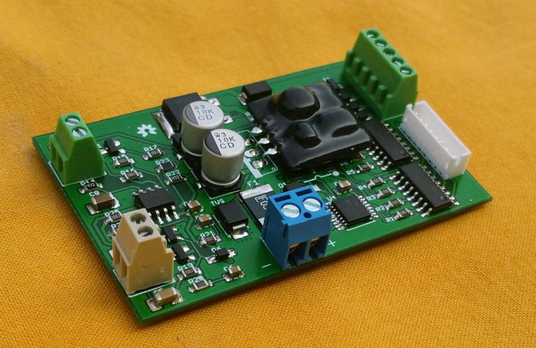
having an issue with a neutral indicator on an aftermarket gauge. in the hopes of someday solving the issue, i've begun troubleshooting individual components to try and isolate the culprit. first up, the TGPI switch itself. 

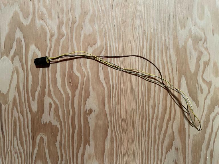
today, after reading through various posts here and at motobrick, i came across a reply from robmack / RBM for how to test the switch. using a multimeter, i began testing for continuity at the male connector for the TGPI where it attaches to the main harness (touching the black lead to the male ground and the red lead to the various yellow/xxx male pins). 

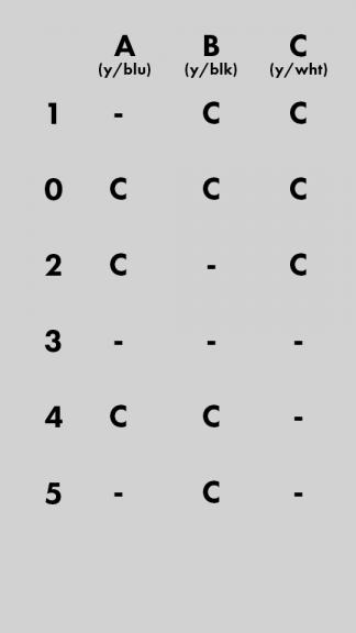
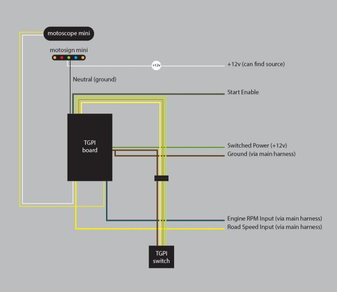
robmack / RBM supplied this image of what continuity readings should be on a properly functioning GPI...

TGPI / GPI troubleshooting (SOLVED) TGPI%252520truth%252520table 

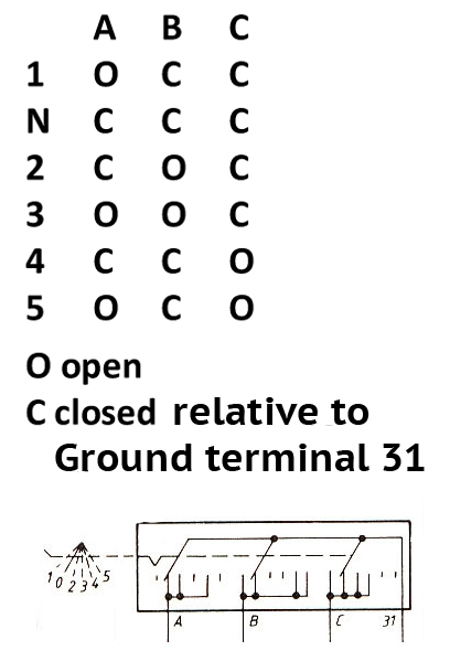
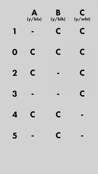
my readings came out quite different, however... which is odd because it's a brand new TGPI switch... 
TGPI / GPI troubleshooting (SOLVED) 4371-020821213106

so some initial questions:

  1. any ideas why the readings are this off? (is it possible the TGPI is mis-aligned inside the housing?)
  2. has anyone ever encountered similar readings?


any help is greatly appreciated.
s


Last edited by thestza on Mon Sep 13, 2021 7:28 pm; edited 2 times in total (Reason for editing : (updated image to match order established in robmack image))


robmack

robmack
Life time member
Life time member
I'll assume that your multimeter was connected properly and the connections were good and sound (no poor connections). I'm not exactly sure how to interpret a "-". Does it mean open circuit?

Your results indicate a defective switch. I'd recommend that you open it and give it an inspection as well as a cleaning.


__________________________________________________
Robert
1987 K75 @k75retro.blogspot.ca
http://k75retro.blogspot.ca/
    

thestza

thestza
active member
active member
i'm also assuming that the multimeter is functioning properly. i performed similar tests with an older unit that i pulled from the bike and was able to get results that were more in line with the supplied graphic. 

the "-" is no continuity (didn't pull actual resistance readings)

definitely need to pull / inspect the unit...


4Back to top Go down   TGPI / GPI troubleshooting (SOLVED) Empty another round of trouble-shooting Mon Aug 02, 2021 10:47 pm

thestza

thestza
active member
active member
pulled the wheel + swing arm and removed the new TGPI switch for testing... i opened up the unit and noticed that two of the pins were sitting low (they were on crushed springs). this sorta gives logic to the incorrect readings but doesn't fully explain it.

so i reinstalled the old unit and shifted through the gears and again tested for continuity / closed circuits between the yellow wires + ground (at pin 31 on the TGPI switch). this yielded much better results! (although there is still a potential something)

NEW READINGS (ON OLD TGPI SWITCH) 
TGPI / GPI troubleshooting (SOLVED) 4371-020821213136

everything matches robmack / RBM's diagram except 3rd (here is robmack's image for reference)
TGPI / GPI troubleshooting (SOLVED) TGPI%252520truth%252520table

so... a mixed bag. key takeaways:

  • confirmed that the new switch was indeed defective (money down the drain there Crying or Very sad
  • sorta promising results with the old unit (still maybe need to figure out the issue with 3rd gear -- but maybe not?)
  • will test the female TGPI wires on the harness side next


any ideas / thoughts for why 3rd might be funky?


Last edited by thestza on Mon Aug 02, 2021 10:53 pm; edited 1 time in total (Reason for editing : typos)


robmack

robmack
Life time member
Life time member
Third is funky because the pin connected to "C" is not making good contact with the copper trace when the transmission is positioned in third gear.  Maybe there is corrosion on the trace, or maybe there is a break in connectivity in the trace.  Open the switch and examine the copper trace for breaks and make sure the copper is shiny and bright (good conductivity).


__________________________________________________
Robert
1987 K75 @k75retro.blogspot.ca
http://k75retro.blogspot.ca/
    

thestza

thestza
active member
active member
thanks robmack. 

updates for today: i removed + cleaned the contacts on the TGPI switch this AM. i then performed the same continuity test again and was able to verify the results! i now have a match to your chart graphic for continuity / closed circuits between the yellow wires + ground (at pin 31 on the TGPI switch). 
TGPI / GPI troubleshooting (SOLVED) 4371-030821180925
TGPI / GPI troubleshooting (SOLVED) TGPI%252520truth%252520table
so a bit of good news there... 


HARNESS CONTINUITY TEST
i then turned my attention to the harness side. using the female TGPI connector + wires from an old / spare harness, i first tested for continuity at the connector to the various wire ends. thankfully, it seems the bit of harness is working properly as all wires had continuity (a quick image showing the portion of old harness).
TGPI / GPI troubleshooting (SOLVED) 4371-030821194949

i then connected the male + female TGPI and re-verified the table above (continuity / closed circuits between the yellow wires + ground but this time through the harness).
TGPI / GPI troubleshooting (SOLVED) 4371-030821195419

so some good news on the whole today. some key takeaways + next steps:

  • i have verified that my TGPI switch is functioning properly
  • even better, the values are transmitting properly through the TGPI connector on the harness side
  • need to now trouble shoot my relay gauge setup
  • related, i will make a diagram that shows how i have everything connected


will post again soon with progress. please chime in if there is an error to my methods here and i've missed something crucial. thanks for the help thus far (robmack, specifically)


robmack

robmack
Life time member
Life time member
Great news.  Cleanliness is next to godliness.  Smile


__________________________________________________
Robert
1987 K75 @k75retro.blogspot.ca
http://k75retro.blogspot.ca/
    

thestza

thestza
active member
active member
robmack wrote:Great news.  Cleanliness is next to godliness.  Smile

definitely movement in the right direction... my neutral light still isn't illuminating so still stuff to troubleshoot, but at least i've eliminated 2 variables!


thestza

thestza
active member
active member
after verifying a functioning TGPI switch + harness, the next components are a TGPI board / relay + aftermarket neutral indicator.

TGPI BOARD / RELAY
currently, i'm using one of robmack's TGPI boards / relays (V5 with tack + speed interface). the unit was purchased new almost 3 years ago. the speed + tach features have been working flawlessly, but i haven't yet gotten the neutral to work (a combination of user error / bad wiring + a faulty switch).
TGPI / GPI troubleshooting (SOLVED) Medium_4371-040821110514

NEUTRAL INDICATOR
as for the neutral indicator, i'm using a motosign mini from motogadget. similarly, this unit was purchased new about 3 years ago. at the moment, the turn signal, oil pressure, and high-beam indicators are all working as they should.
TGPI / GPI troubleshooting (SOLVED) Medium_4371-040821110534

TROUBLESHOOTING FIRST STEPS

  • test neutral indicator light
  • re-read TGPI board / relay manual
  • create wiring schematic(s) 


NETURAL LIGHT TEST
to test the indicator light, i first verified that the black cable on the motosign mini was attached to ground.  then, i ran a temporary jumper / patch from the green / black switched power at fuse 1 to the white cable of the motosign mini. the bulb works so that's good!
TGPI / GPI troubleshooting (SOLVED) Medium_4371-040821112048

RE-READ TGPI BOARD / RELAY MANUAL
there are a couple of sections that caught my eye upon re-read:
TGPI / GPI troubleshooting (SOLVED) Medium_4371-040821114126

i'm learning as i go with regard to electricity... but this is how i understand those first two sentences (please forgive my basic graphics here). in the abstract, is this correct?
TGPI / GPI troubleshooting (SOLVED) Medium_4371-040821130633


robmack

robmack
Life time member
Life time member
Yes, that's a correct depiction of what's happening inside the TGPI board.  I'll assume that your LED in the drawing is "12V LED" so then your schematic symbols are accurate.

Because you haven't had luck with the neutral light, I assume that you also haven't yet got the Start Enable circuitry to work either?


__________________________________________________
Robert
1987 K75 @k75retro.blogspot.ca
http://k75retro.blogspot.ca/
    

thestza

thestza
active member
active member
thank you for clarifying robmack! this is extremely helpful, and i hope i can use this knowledge to correct my previous error(s). in past attempts, i had envisioned the the TGPI board to function more like this (as a gate / switch that either blocked or allowed flow on the +12v anode side):
TGPI / GPI troubleshooting (SOLVED) Medium_4371-040821193428

PREVIOUS / INCORRECT FULL WIRING DIAGRAM
as such, this is how i had wired the board previously: +12v flowing from TGPI board --> anode on LED indicator --> ground
TGPI / GPI troubleshooting (SOLVED) Medium_4371-040821193931


UPDATED / CORRECT FULL WIRING DIAGRAM
if i understand correctly, this is how it should be wired with my current setup: +12v to anode on LED indicator --> cathode on LED indicator to TGPI board --> ground 
TGPI / GPI troubleshooting (SOLVED) Medium_4371-040821194622


am i correct that this updated wiring diagram is more accurate to how the board should actually be wired (with my specific setup)?

RE: your question about the Start Enable Circuity, your assumption is correct. it is not functioning either... (i've never really missed it however, as i always just pull the clutch in anyhow)

thanks again for the help!


12Back to top Go down   TGPI / GPI troubleshooting (SOLVED) Empty Re: TGPI / GPI troubleshooting (SOLVED) Thu Aug 05, 2021 12:49 am

robmack

robmack
Life time member
Life time member
Yes, your revised schematic is correct.  +12V goes to the Neutral LED anode and the neutral LED cathode goes to the TGPI board.


__________________________________________________
Robert
1987 K75 @k75retro.blogspot.ca
http://k75retro.blogspot.ca/
    

thestza

thestza
active member
active member
thanks robmack. hoping i can dig into the harness and test this out over the weekend. will report back soon.


thestza

thestza
active member
active member
tore apart the harness this weekend and made some temp / crappy connections...  the updated wiring schematic worked – I HAZ NEUTRAL!!!!!!!!!!!!!!!!!!!!!!!!!!!!!!!!!!!!!!!!!!!!!

TGPI / GPI troubleshooting (SOLVED) 723598TGPI / GPI troubleshooting (SOLVED) 723598TGPI / GPI troubleshooting (SOLVED) 723598TGPI / GPI troubleshooting (SOLVED) 723598TGPI / GPI troubleshooting (SOLVED) 723598 
TGPI / GPI troubleshooting (SOLVED) 447221TGPI / GPI troubleshooting (SOLVED) 447221TGPI / GPI troubleshooting (SOLVED) 447221TGPI / GPI troubleshooting (SOLVED) 447221TGPI / GPI troubleshooting (SOLVED) 447221TGPI / GPI troubleshooting (SOLVED) 447221TGPI / GPI troubleshooting (SOLVED) 447221TGPI / GPI troubleshooting (SOLVED) 447221TGPI / GPI troubleshooting (SOLVED) 447221TGPI / GPI troubleshooting (SOLVED) 447221
TGPI / GPI troubleshooting (SOLVED) 723598TGPI / GPI troubleshooting (SOLVED) 723598TGPI / GPI troubleshooting (SOLVED) 723598TGPI / GPI troubleshooting (SOLVED) 723598TGPI / GPI troubleshooting (SOLVED) 723598 

i'll need to upgrade from a 6pin to an 8pn connector. hoping to make nicer splices / actual solders / clean the harness this weekend.

photo evidence to come soon.

thanks robmack!


thestza

thestza
active member
active member
quick follow here. finally had a minute to clean up the harness. went to take the bike out and enjoy my fancy new neutral light. it started initially but died... 

tried starting again but the was too tired to fire up...

re-charged the battery but now the bike won't turn over when i press the ignition (no clicking, no whirling, nothing). have been digging around for possible causes and it seems that either the starter or relay are to blame. will follow up here (or in a new thread with some initial testing).


robmack

robmack
Life time member
Life time member
You tried pulling in the clutch handle?


__________________________________________________
Robert
1987 K75 @k75retro.blogspot.ca
http://k75retro.blogspot.ca/
    

thestza

thestza
active member
active member
hi robmack. yes, not getting anything with bike in neutral and / or with clutch lever pulled in.


18Back to top Go down   TGPI / GPI troubleshooting (SOLVED) Empty Re: TGPI / GPI troubleshooting (SOLVED) Mon Aug 30, 2021 10:32 pm

robmack

robmack
Life time member
Life time member
It could possibly be the ignition switch or kill switch.  Test for power on the Green wire on the ignition switch when in "On" position (test on Load Shed Relay connector in relay box).  Check for power on Green/Yellow on kill switch in "Normal" position (test at Fuse1)..

Follow Bert's guide on troubleshooting starting problems, available in the downloads section of this site.


__________________________________________________
Robert
1987 K75 @k75retro.blogspot.ca
http://k75retro.blogspot.ca/
    

19Back to top Go down   TGPI / GPI troubleshooting (SOLVED) Empty Re: TGPI / GPI troubleshooting (SOLVED) Mon Aug 30, 2021 11:50 pm

thestza

thestza
active member
active member
thanks as usual robmack.

a quick follow to the tests you suggested.

Test for power on the Green wire on the ignition switch when in "On" position (test on Load Shed Relay connector in relay box)

  • at the green wire (pin 86 in the LSR) with the ignition in the "On" position, i was reading 12.39V


Check for power on Green/Yellow on kill switch in "Normal" position (test at Fuse1)

  • at the green / yellow wire (at fuse 1) and the kill switch in "normal" position (middle, facing directly up), i also measured 12.39V


i will definitely check out Bert's guide. thanks again for the help.

s


Sponsored content


View previous topic View next topic Back to top  Message [Page 1 of 1]

Permissions in this forum:
You cannot reply to topics in this forum