BMW K bikes (Bricks)


You are not connected. Please login or register

View previous topic View next topic Go down  Message [Page 1 of 1]


Rampa

Rampa
active member
active member
Hi.

My motorcycle is a bmw k100 16v and I am using the BEP 3.0 interface which is theoretically compatible with the ACEWELL 4453 speedometer.

I'm having trouble setting the speed and odometer, as well as setting the engine temperature.

I have the green wire connected to the "SPD" socket of the BEP as indicated in Acewell's instructions and the purple wire is connected to GND.

Problems with Acewell 4453 + Bep 3.0 speed and temp Escane10

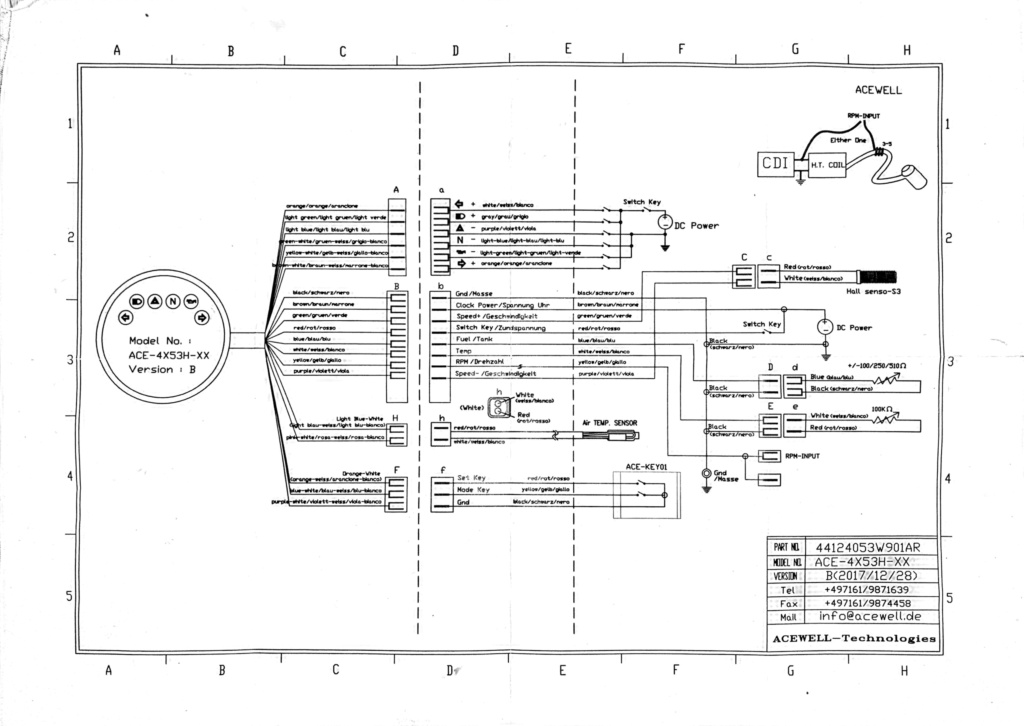
The pulse counter in the acewell is at P-006 and my wheel is 17 ", however it does not work, it does not indicate speed or count the km traveled.

I have checked the sensor with the original speedometer and it works correctly ...


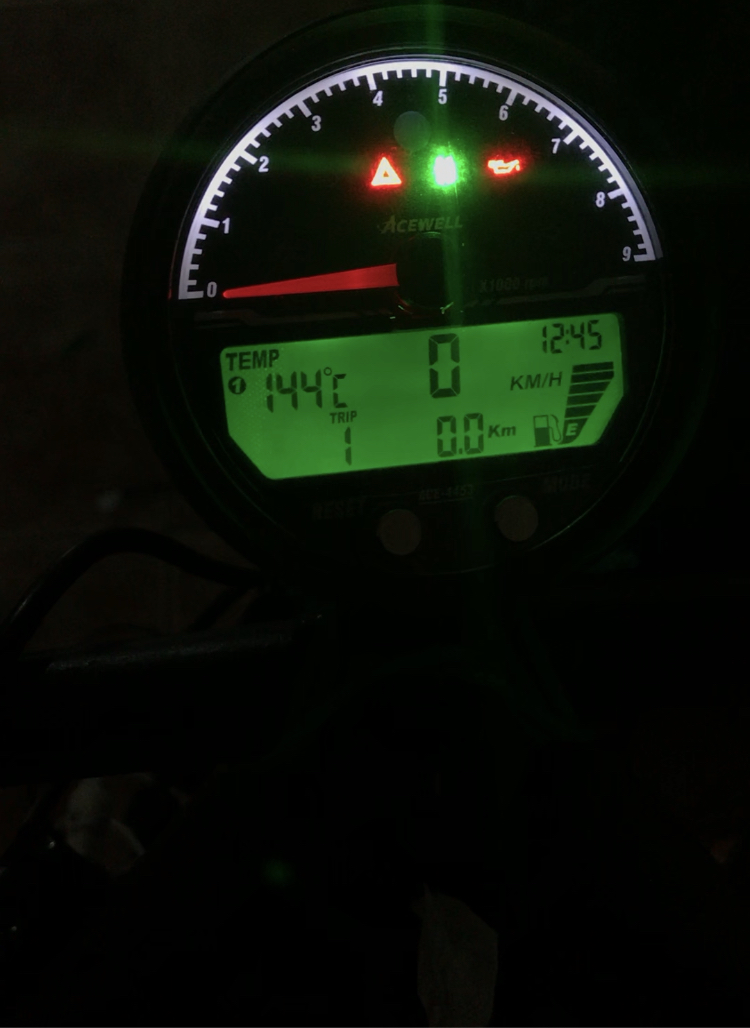
I am also having problems with the engine temperature, when I connect the white wire (Temp) the speedometer goes crazy and indicates a very high temperature with the engine stopped and cold.

Problems with Acewell 4453 + Bep 3.0 speed and temp Img_8810

I have sent an email to Acewell to see if they can help me, but I still have not received a response ...

I hope that you can help me and as soon as Acewell's answer me, I will let you know and leave the solution written in case a colleague needs it.


Thank you very much and excuse my bad English. Rolling Eyes


robmack

robmack
Life time member
Life time member
You have connected the Acewell speed sensing circuit incorrectly. SPEED+ (green) is a voltage supply for the Hall Effect sensor that comes with the gauge.  SPEED- (purple) is the speed signal input coming from the Hall Effect sensor.  Connect purple to SPD on the BEP; leave green unconnected.

Also, you are supposed to program the circumference of the WHEEL, not the diameter of the RIM.  The rear wheel circumference is somewhere around 2000mm.  Play around with the value of this number to dial in the accuracy of the speedometer.

The Acewell is expecting a variable resistor sensor to be connected to TEMP (white).  You've connected an on-off switch to that wire instead. The TMP output from the BEP is an on-off over-temperature signal, and not an analogue representation of the water temperature.  So, don't do that.  Either use one of the indicator lights on the gauge to show over temperature or buy a compatible water drain plug, install it in the water pump, and connect it to the Acewell -- as you would have done if you were to install the OEM auxillary fuel/temp gauges.


Last edited by robmack on Sat Oct 03, 2020 12:28 pm; edited 2 times in total


__________________________________________________
Robert
1987 K75 @k75retro.blogspot.ca
http://k75retro.blogspot.ca/
    

Laitch

Laitch
Life time member
Life time member
robmack wrote:. . . you are supposed to program the circumference of the WHEEL, not the diameter of the RIM.  The rear wheel circumference is somewhere around 2000mm.  
In some places, the words wheel and rim denote the same object. The circumference of the tire is needed.


__________________________________________________
1995 K75 90,000 miles
    

Rampa

Rampa
active member
active member
Hi, thank you for you answer.
I have tried to connect the purple cable to SPD and I have set the wheel to approx 2000.
Even so, no matter how much I turn the wheel the speedometer still does not show the speed or the km.


Laitch

Laitch
Life time member
Life time member
Rampa wrote:I have tried to connect the purple cable to SPD and I have set the wheel to approx 2000.
If the purple wire was connected to GND but is now connected to SPD as was suggested, have you connected a wire to GND?


__________________________________________________
1995 K75 90,000 miles
    

robmack

robmack
Life time member
Life time member
Laitch ,  the BEP provides the required grounding for the system including grounding one side of the speed sensor. I suspect that the OP has properly grounded the Acewell because all other functions are working. That means if a signal is piped into purple, it should be properly referenced to ground.

I’d check to see if there’s any output on SPD on the BEP. use a multimeter to look for a voltage variance as you manually spin the rear wheel. If none then there’s a problem with the BEP. If there is a variance then the problem is with the Acewell.


Last edited by robmack on Sat Oct 03, 2020 10:13 pm; edited 1 time in total


__________________________________________________
Robert
1987 K75 @k75retro.blogspot.ca
http://k75retro.blogspot.ca/
    

Rampa

Rampa
active member
active member
Good afternoon.

I have disconnected all cables, crimped them and reconnected them correctly. Still not working. I have tried to measure the ohms coming out of SPD and the tester does not detect anything: Crying or Very sad


However I test it reaches the original connector the sensor varies the intensity as I move the wheel:


I'm going to have to contact the vendor that sold me the BEP 3.0 to see what solution it can give me.


Thank you very much for you time, I will keep they informed


robmack

robmack
Life time member
Life time member
Please put the multimeter on DC volts setting, not ohms. You want to measure voltage coming out of the BEP. Even spinning the wheel by hand should register changes on the voltmeter. The rear sensor should put out about 2 volts AC peak to peak. The SPD output of the BEP should put out about 0 - 10 volts.  That is you should see the voltmeter change 6 times per revolution swinging between 0 volts and 10 volts or so doing so suddenly because the BEP outputs a square wave.


__________________________________________________
Robert
1987 K75 @k75retro.blogspot.ca
http://k75retro.blogspot.ca/
    

Rampa

Rampa
active member
active member
Good morning.

I have tried as you have told me and I am still not clear: here is a video with the red cable of the tester in the SPD and the black cable to ground.

https://youtu.be/hGx3CaBQJeQ

now another video with the red cable to positive and the black to the SPD
https://youtu.be/ooJrIk4wno8

I can't understand why it doesn't work


robmack

robmack
Life time member
Life time member
The ideal test tool in this instance would be an oscilloscope, but I assume you don't have one or don't have access to one.  So, the only tool available to you would be the voltmeter.  You want to make measurements relative to ground so black test lead on battery -ve.  The problem with the voltmeter is its response time; it's too slow to respond to the changing voltage levels.  This is what you are seeing in the first video.  It appears that there is a signal coming out of SPD (I'm assuming that you are spinning the rear wheel while recording) because the bar graph indicator at the bottom of the display is responding.  

I just checked the wiring diagrams for two different Acewell gauges, the Acewell 2853 and MA085.  Both also have SPEED+ and SPEED- wires. The SPEED- wire on the 2853 gauge goes directly to ground according to its wiring diagram.  Marulabs' suggests hooking up the MA085's SPEED+ wire to SPD.  So, maybe I was incorrect to tell you that purple was the input.  Based on this information, Acewell's SPEED+ (green) is the input. Sorry to mislead you.

Why your Acewell is not reacting to the signal I don't know.  I can't imagine that the Acewell is broken.  You might want to prod Acewell support again to find out how to wire up a speed sensor that is not the Hall Effect sensor that came with the gauge.  Try to hook up the Hall Effect sensor to the gauge and temporarily set it up according to the instructions in the Acewell manual to make it work.  That will allow you to test the Acewell speedo function and verify it's working.

Instead of the voltmeter to measure the SPD output, you could use a LED.  It will respond very quickly to the changing signal.  However, this will only confirm what I think is the case; the SPD output is working.

I'm running out of ideas.


__________________________________________________
Robert
1987 K75 @k75retro.blogspot.ca
http://k75retro.blogspot.ca/
    

Rampa

Rampa
active member
active member
Hello!  I have done several tests. 

I have connected the green wire to SPD but it still does not work.


So I tried to connect the hall sensor that comes with the Acewell and it works!  we can rule out that the problem is Acewell.


Is it possible that the BEP is broken?  I have tried to do the test with a led diode but it always stays on.

 
I connected the original speedometer again and I have done 2 tests, one with the sensor removed (bringing it closer to a transformer) to check its operation, it works correctly. (I did the Acewell tests with the sensor placed on the cardan and with the sensor attached to a transformer) 


But if I put the sensor on the cardan the needle does not move.  although this is another topic ...


robmack

robmack
Life time member
Life time member
You've eliminated the Acewell as a potential defect, and the rear wheel sensor and wiring as a potential defect. so, it's looking more like the BEP is defective. The LED should flicker in sync with the revolving rear wheel.


__________________________________________________
Robert
1987 K75 @k75retro.blogspot.ca
http://k75retro.blogspot.ca/
    

Rampa

Rampa
active member
active member
I spoke with the seller and they are going to change it for me. As soon as I have the new unit I will tell them if it works.

Thank you very much for the help. Very Happy


Rampa

Rampa
active member
active member
Hi.

I changed my BEP unit. I plugged it in and tested it, I got the wheel to read 8 km/h while moving and tightening the cables, however it stopped working ... I think it's a wiring problem ...

I have bought a new speed sensor, but it neither does not work.

As I was suspicious of the connector, I decided to change it

Problems with Acewell 4453 + Bep 3.0 speed and temp Img_9010

however it doesn't work either.

Attached a video of the interior of the cardan:


I see it well.


Can you tell me what's going on? it's really frustrating  Crying or Very sad


Laitch

Laitch
Life time member
Life time member
Rampa wrote: ... I think it's a wiring problem ...
You need to review your wiring of the BEP to the Acewell. Perhaps you could post a photo of the BEP and the Acewell plugs wired into it.

Your Brick's speed sensor was working with the Brick's instrument cluster and so were the instrument's plugs so they were ok. Hopefully the new plugs were correctly wired.


__________________________________________________
1995 K75 90,000 miles
    

robmack

robmack
Life time member
Life time member
Trace your steps back and see if your actions contributed to the problem.

So, as I understand it, you installed the new BEP using the existing wiring you had installed before the exchange. You spun the rear wheel by hand and it registered a reading. Then you started to secure the loose wiring and suddenly you couldn't get a reading after completing that work. You then exchanged the VR sensor in the rear drive for a new one and it too did not work.

I would guess the problem is wiring, and related to an intermittent connection somewhere in the VR sensor circuit. That could be the connector under the battery cover or the connection to the BEP. I'd suggest separating the VR sensor connector and see if you can clean the contacts with contact cleaner like Deoxit. Also use a small jeweller's screwdriver to try and slightly close the female connector so that there is better contact between the pins.


__________________________________________________
Robert
1987 K75 @k75retro.blogspot.ca
http://k75retro.blogspot.ca/
    

Sponsored content


View previous topic View next topic Back to top  Message [Page 1 of 1]

Permissions in this forum:
You cannot reply to topics in this forum