BMW K bikes (Bricks)


You are not connected. Please login or register

View previous topic View next topic Go down  Message [Page 1 of 1]


PaulM

PaulM
New member
New member
Hi,


We are having a small issue with a bep 3.0.

To summarize:
We are rebuilding an early K100 with m-unit and are using the BEP 3.0 only for:
- Gear Neutral indicator ( is working )
- Speedo

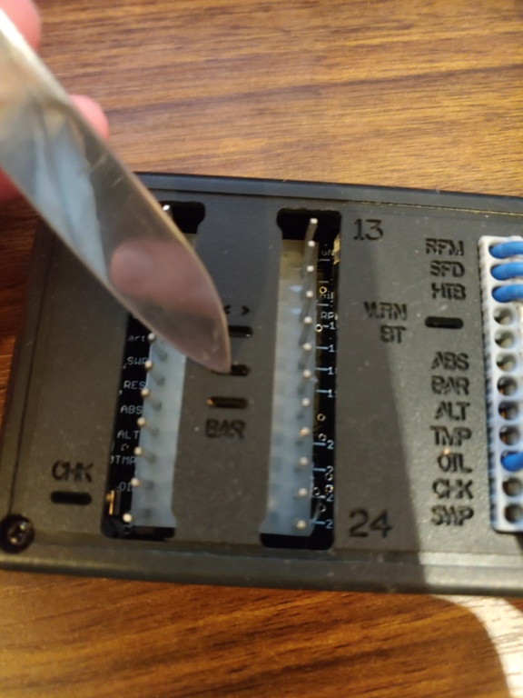
The BEP is powered using pin 6: Zündungplus
Masse is provided using pin 13

Pin 22 (induktivgeber endantrieb) has the yellow wire coming from the speed sensor from the rear.
The masse from the speed sensor is connected to the general Masse/Ground.
The ACEwell Speedo its speed-cable(green) is connected to the BEP 3.0 Outpost: SPD.

Unfortunately, we don't get any result.
Does the BEP unit need certain mass or power connections to make the SPD function work ?

Thank you,
Kind regards,

Paul


robmack

robmack
Life time member
Life time member
The connections that you described are correct. There are no special power or ground (masse) requirements. The Acewell needs to obtain its power from the BEP. BAT should go to the wire for unswitched power on the Acewell and SWP should go to the wire for switched power on the Acewell and GND to the Acewell's ground connection.

Is it possible to connect an oscilloscope from SPD to GND to see whether the BEP is outputting a signal? If you don't have an oscilloscope, you can use a LED. You'd spin the rear wheel and look for a signal on the oscilloscope or the LED blinking in unison with the wheel spinning.


__________________________________________________
Robert
1987 K75 @k75retro.blogspot.ca
http://k75retro.blogspot.ca/
    

3Back to top Go down   BEP Speed Output - Minimal required connections to BEP Empty *going nuts* Sun Nov 22, 2020 1:54 pm

PaulM

PaulM
New member
New member
Ok,  it took a while to run all diagnostics/replacements without any positive result :/

I'm running out of idea's, any help or fresh idea would be appreciated.

So far:


  1. With the magnet sensor from Acewell: Speedo works. (green wire) Speedo: CA85-X51
  2. Replaced BEP with Alex-box: same result
  3. Replaced Rear Sensor with a brand new one: same result
  4. The 2 wires (brown/yellow) are now both directly connected to the BEP. Pin 22(yellow), Pin 23(brown).
  5. I measure 12v from SPD output from the BEP. ( not changing when rotating the wheel )
  6. Looking into the rear hub, all looks fine.
  7. Changed/played around with the HALL/REED settings on the Acewell. ( getting desperate Crying or Very sad )


So, who has another idea to try?

In the BEP documentation, it shows:
SPD speed amplified and adjustable between 0 - 5V or 0 - 12V

How is this adjustable? I've seen the 4 switches on the unit which have other functions.

Thanks,

hopefull to find a solution soon as this is the only thing left to fix on the bike.

//Paul


robmack

robmack
Life time member
Life time member
What is the resistance you measure between pin 22 (yellow) and 23 (brown) with the OEM connector disconnected from the Brotdosenadapter?  If you read open circuit, I would be suspicious of the wiring or harness connectors.

Also, how are you measuring the response on the SPD line?  Using a voltmeter?  If so, it's quite possible that the meter you have does not have the response time characteristics that will allow it to show changes in level that occur on the SPD line.  The duty cycle of the signal is 10% or less and a voltmeter can't respond that fast. In this case, the best instrument is an oscilloscope.


__________________________________________________
Robert
1987 K75 @k75retro.blogspot.ca
http://k75retro.blogspot.ca/
    

Wiz

Wiz
Silver member
Silver member
I think I might know what issue you are having, though this is just an off the top of my head thought, but by chance are you trying to connect an analog signal to a digital speedo circuit? meaning, analog is a voltage where 0v is stopped, and 5v or 12v represents an arbitrary max speed setting, where a digital signal (more common by far, and probably what the acewell is looking for), a pulses per revolution of the wheel in order to calculate the speed of the vehicle by means of knowing the diameter of the wheel and frequency of the sensors reading? 


I will take a look at the bep 3.0's documentation and the acewell too and see if I can get you an answer.

EDIT: Im looking at the documentation for both products here and they both say they are meant to use a digital signal. The speed output from the BEP 3.0 should be a square wave, so I cant see any reason why it wouldn't work if you set it up correctly.

Things I suggest you try are:

1: Make sure you have the circumference of the rear tire set correctly (in the acewell)
2: Make sure you have your pulses per revolution "SPD P-XXX" set to 12 pulses iirc for the k100 rear end (also in acewell)
3: Make sure you have the acewell gauge set to rEED mode (as described in the documentation) (in acewell)
4: This goes without saying but make sure you have the BEP 3.0 plugged in with the wires down, and the correct wires from the acewell connected to the BEP.
5: You mentioned the BEP says it can be adjusted from 0-5V and 0-12V, What this is referring to is the formation of the square wave, its meaning that the square wave will spike to(or in this case drop to zero from) either 5v or 12v indicating a pulse from the rear wheel, I would recommend that if the steps above do not work, try changing the BEP to a different voltage mode, the switch to change this is shown in the picture I attached, the middle slot has a switch below it, default it should be in the left position looking at the BEP right side up, this is 5v mode, and moving it to the right switches it to 12v mode, if the steps above do not fix it, move this switch to the right, and that should enable the acewell to read the pulses from the BEP.

I hope this helps you

Wiz

BEP Speed Output - Minimal required connections to BEP 11232010


Sponsored content


View previous topic View next topic Back to top  Message [Page 1 of 1]

Permissions in this forum:
You cannot reply to topics in this forum