1

 RPM Signal Conditioning Circuit to prevent aftermarket tachometer needle instability Mon Aug 07, 2017 3:52 pm
robmack
Life time member

From time to time, guys who are modifying their K-bike to use an aftermarket gauge will post threads about the tachometer being unstable. The symptoms are that at idle or even certain engine speeds, the tach needle will vary widely in its indication. The question is usually around how to fix this problem. The common recommendation is to add a low pass filter to the tachometer input of the gauge to get rid of the frequencies above 5KHz. This solution is variable in its success.
I tried tackling the problem today and met with pretty good success with a circuit that is a bit more complex that a simple filter.
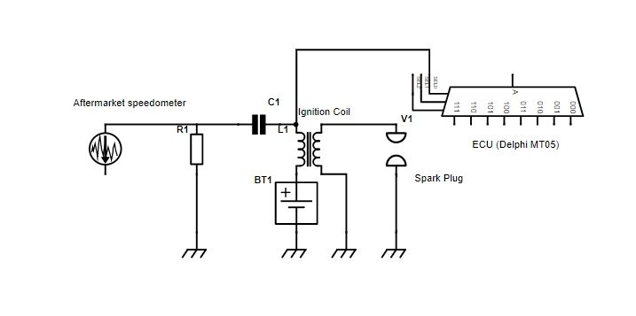
The classic K-bike in all its variants from the early K100s through the K75s to the K1100s tap off the primary winding of the #1 cylinder sparking coil. This signal is fed to the OEM cluster on the tachometer board pictured below.
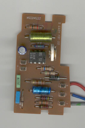
You'll notice the IC, a SAK 215, which is a Pulse Shaper Circuit for Revolution Counters. Basically this circuit takes the raw input signal and outputs a current proportional to the speed of the engine, and this current directly drives the tachometer needle on the gauge. Unfortunately, if you think that you can re-purpose this card, then you will find that it will not work with a modern aftermarket tachometer because the modern tachometer is expecting a series of digital pulses and not a proportional analog current.
The signal coming off the primary of the Cylinder #1 coil (Black/Red wire to Pin 16) looks like the picture below (this was taken using my oscilloscope while probing my K75). All the testing was photographed at idle speed of about 1000 RPM:
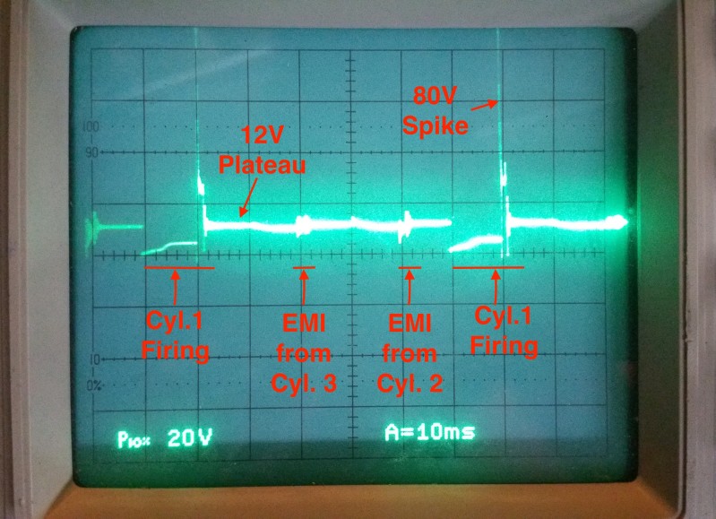
The ground reference is in the line in the middle of the screen with all the tick marks. You can see the signal normally rests at 12V above ground (what I've labelled as the 12V plateau) and is equal to the input voltage on the far side of the primary. Each vertical line represents 20 volts and each horizontal line represents 10 mS. When the ICU commands the coil to fire, it asserts ground which causes the signal to drop to ground potential for 10mS and then the ICU cuts the ground signal causing a large voltage spike of about 80 Volts in the primary. This spike gets amplified by the coil and causes the spark across the plug. The other anomalies you can see are electromagnetic interference (EMI) from the adjacent coils on the K75 for Cylinders 2 and 3. The signals mix together because of magnetic coupling and causes noise on the lines. It is this variable signal along with the noisy EMI that causes instability in the RPM signal, unless the signal is properly conditioned.
This signal has far too much noise and anomalies on it so it needs to be conditioned to make it compatible with the aftermarket gauge. The gauge is expecting a clean square wave (as what would be found coming off the HALL Sensor array, for example). The circuitry I've devised to do such conditioning is shown below.
Power Supply

Conditioning Circuit

How does it work:
I'll first talk about the power supply and then the conditioning circuit
The circuit requires 12 volts to power the output driver and 5 volts to power the rest of the circuit. It gets 12 volts from the power input on Jack J1. To get 5 volts, I've used a 3-terminal regulator, LM2940N. The diodes D1, D2 and fuse F1 are completely optional and protect the regulator from damage. The capacitor C1 is required and C2 is optional. The 5 volt rail is used to power the IC and the first two stages of the conditioner.
The conditioner circuit consists of three stages. So, how does this circuit work? It looks complex but it's not (really).
First, the K75 coil #1 input goes to a capacitor, C3, to remove the 12V plateau. The signal is next fed to a 10:1 voltage divider consisting of R1/R2 which reduces the 80V spike into an 8V spike. The capacitor R1/C4 forms a Low Pass filter to reduce ringing in the signal. This pre-conditioned input is fed to a NPN transistor, T1. The diode D3 ensures that any negative going signal components are cut off a -0.7V and don't harm T1. The output on the collector of T1 is lengthened through an R-C time stretching circuit consisting of R3/C5 to about 1.5mS. This signal appears as shown below:

The signal is 5V p-p with a duration of about 1 mS - 1.5 mS. You'll notice that the signal is unstable and rounded in its shape. This signal may possibly be used as is but I can do better. I fed it into the second stage, a schmitt trigger circuit comprised of a LM2904/LM358 dual general purpose op-amp, IC2, and resistors R4, R5 and R6. A schmitt trigger is a special circuit that will clean up the signal and make the pulse width more consistent and make the shape of the output more square. The output from the Schmitt trigger is shown below:

This shows regular 4V pulses of 1.5mS duration. The third stage of the circuit is to make the signal compatible with any aftermarket gauge. The output needs to be negative going and 12V p-p in amplitude. To accomplish this, the Schmitt trigger is fed to an Open-collector driver consisting of a single NPN transistor, T2 and resistor R7. This driver inverts the signal and protects the upstream circuitry from damage. The resistor R8 is a pull-up resistor. When the transistor T2 is off, this resistor ensures that the output rises to 12 volts, guaranteeing that the output voltage swing will be from 0V to 12V.
So, know that you know what's going on, the image below compares the input signal and the output signal :

What you are seeing is the trace on the bottom of the screen being the input signal on X1-1 in the schematic above. The upper trace is the output signal on X1-2. The lower signal is represented by 20V per division and the upper signal by 5V per division. Each vertical division is 10mS. You can see that exactly when the coil #1 primary fires, a 1.5mS negative going pulse is produced on the output. The amplitude of that pulse is 12 volts because I tied the open-collector output to +12 volt source. This pulse again repeats when the next time coil #1 fires.
This circuit should stop the annoying bouncing of the tachometer needle on aftermarket gauges. I'd be interested to hear of any experiences with this circuit should some here decide to build it. I am planning on integrating this circuit into the next version of my TGPI board.
Annoying Chinese Motorcycle Gauge
A popular gauge to use for many K100 conversions is the "12000 RPM Motorcycle Gauge" pictured below:

There are many features/functions of this gauge which are annoying, but the one big one for me was the tachometer feature. This gauge is unlike any other gauge available from other manufacturers in that its tacho input requires the engine speed signal to go negative relative to ground. This is annoying because it's hard to to generate voltages below the level of the frame ground. However, for this particular gauge, the capacitor C7 and resistor R14 accomplish the task. These two components are only strictly needed for this Chinese gauge, otherwise all aftermarket gauges function well without these components.
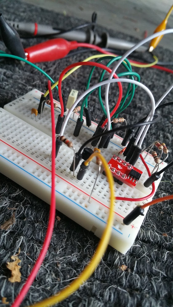
Test Setup
BTW, this is a picture of my test setup:

P.S. Don't have an oscilloscope? No problem, use the sound card on your PC as an oscilloscope.
I tried tackling the problem today and met with pretty good success with a circuit that is a bit more complex that a simple filter.
The classic K-bike in all its variants from the early K100s through the K75s to the K1100s tap off the primary winding of the #1 cylinder sparking coil. This signal is fed to the OEM cluster on the tachometer board pictured below.
You'll notice the IC, a SAK 215, which is a Pulse Shaper Circuit for Revolution Counters. Basically this circuit takes the raw input signal and outputs a current proportional to the speed of the engine, and this current directly drives the tachometer needle on the gauge. Unfortunately, if you think that you can re-purpose this card, then you will find that it will not work with a modern aftermarket tachometer because the modern tachometer is expecting a series of digital pulses and not a proportional analog current.
The signal coming off the primary of the Cylinder #1 coil (Black/Red wire to Pin 16) looks like the picture below (this was taken using my oscilloscope while probing my K75). All the testing was photographed at idle speed of about 1000 RPM:
The ground reference is in the line in the middle of the screen with all the tick marks. You can see the signal normally rests at 12V above ground (what I've labelled as the 12V plateau) and is equal to the input voltage on the far side of the primary. Each vertical line represents 20 volts and each horizontal line represents 10 mS. When the ICU commands the coil to fire, it asserts ground which causes the signal to drop to ground potential for 10mS and then the ICU cuts the ground signal causing a large voltage spike of about 80 Volts in the primary. This spike gets amplified by the coil and causes the spark across the plug. The other anomalies you can see are electromagnetic interference (EMI) from the adjacent coils on the K75 for Cylinders 2 and 3. The signals mix together because of magnetic coupling and causes noise on the lines. It is this variable signal along with the noisy EMI that causes instability in the RPM signal, unless the signal is properly conditioned.
This signal has far too much noise and anomalies on it so it needs to be conditioned to make it compatible with the aftermarket gauge. The gauge is expecting a clean square wave (as what would be found coming off the HALL Sensor array, for example). The circuitry I've devised to do such conditioning is shown below.
Power Supply
Conditioning Circuit
How does it work:
I'll first talk about the power supply and then the conditioning circuit
The circuit requires 12 volts to power the output driver and 5 volts to power the rest of the circuit. It gets 12 volts from the power input on Jack J1. To get 5 volts, I've used a 3-terminal regulator, LM2940N. The diodes D1, D2 and fuse F1 are completely optional and protect the regulator from damage. The capacitor C1 is required and C2 is optional. The 5 volt rail is used to power the IC and the first two stages of the conditioner.
The conditioner circuit consists of three stages. So, how does this circuit work? It looks complex but it's not (really).
First, the K75 coil #1 input goes to a capacitor, C3, to remove the 12V plateau. The signal is next fed to a 10:1 voltage divider consisting of R1/R2 which reduces the 80V spike into an 8V spike. The capacitor R1/C4 forms a Low Pass filter to reduce ringing in the signal. This pre-conditioned input is fed to a NPN transistor, T1. The diode D3 ensures that any negative going signal components are cut off a -0.7V and don't harm T1. The output on the collector of T1 is lengthened through an R-C time stretching circuit consisting of R3/C5 to about 1.5mS. This signal appears as shown below:
The signal is 5V p-p with a duration of about 1 mS - 1.5 mS. You'll notice that the signal is unstable and rounded in its shape. This signal may possibly be used as is but I can do better. I fed it into the second stage, a schmitt trigger circuit comprised of a LM2904/LM358 dual general purpose op-amp, IC2, and resistors R4, R5 and R6. A schmitt trigger is a special circuit that will clean up the signal and make the pulse width more consistent and make the shape of the output more square. The output from the Schmitt trigger is shown below:
This shows regular 4V pulses of 1.5mS duration. The third stage of the circuit is to make the signal compatible with any aftermarket gauge. The output needs to be negative going and 12V p-p in amplitude. To accomplish this, the Schmitt trigger is fed to an Open-collector driver consisting of a single NPN transistor, T2 and resistor R7. This driver inverts the signal and protects the upstream circuitry from damage. The resistor R8 is a pull-up resistor. When the transistor T2 is off, this resistor ensures that the output rises to 12 volts, guaranteeing that the output voltage swing will be from 0V to 12V.
So, know that you know what's going on, the image below compares the input signal and the output signal :
What you are seeing is the trace on the bottom of the screen being the input signal on X1-1 in the schematic above. The upper trace is the output signal on X1-2. The lower signal is represented by 20V per division and the upper signal by 5V per division. Each vertical division is 10mS. You can see that exactly when the coil #1 primary fires, a 1.5mS negative going pulse is produced on the output. The amplitude of that pulse is 12 volts because I tied the open-collector output to +12 volt source. This pulse again repeats when the next time coil #1 fires.
This circuit should stop the annoying bouncing of the tachometer needle on aftermarket gauges. I'd be interested to hear of any experiences with this circuit should some here decide to build it. I am planning on integrating this circuit into the next version of my TGPI board.
Annoying Chinese Motorcycle Gauge
A popular gauge to use for many K100 conversions is the "12000 RPM Motorcycle Gauge" pictured below:
There are many features/functions of this gauge which are annoying, but the one big one for me was the tachometer feature. This gauge is unlike any other gauge available from other manufacturers in that its tacho input requires the engine speed signal to go negative relative to ground. This is annoying because it's hard to to generate voltages below the level of the frame ground. However, for this particular gauge, the capacitor C7 and resistor R14 accomplish the task. These two components are only strictly needed for this Chinese gauge, otherwise all aftermarket gauges function well without these components.
Test Setup
BTW, this is a picture of my test setup:
P.S. Don't have an oscilloscope? No problem, use the sound card on your PC as an oscilloscope.
Last edited by robmack on Sat Apr 14, 2018 7:53 pm; edited 10 times in total
__________________________________________________
Robert
1987 K75 @k75retro.blogspot.ca


 K100RS Style Black 1987 105K Km