BMW K bikes (Bricks)


You are not connected. Please login or register

View previous topic View next topic Go down  Message [Page 1 of 1]


charlie99

charlie99
VIP
VIP
our mate rickg has got himself  aftermarket instruments

he tells me that the gear shift indication is ground switched

so our gearshift switch uses  what they call "bcd" encoding (binary coded decimal )

im in the process of making him something that might make it easy to interface

firstly the gearchange needs to be put back to decimal for his instruments (separate wire for each gear selected )
second will be a pulse circuit for the rear wheel sensor

but first off lets explore the bcd decoding

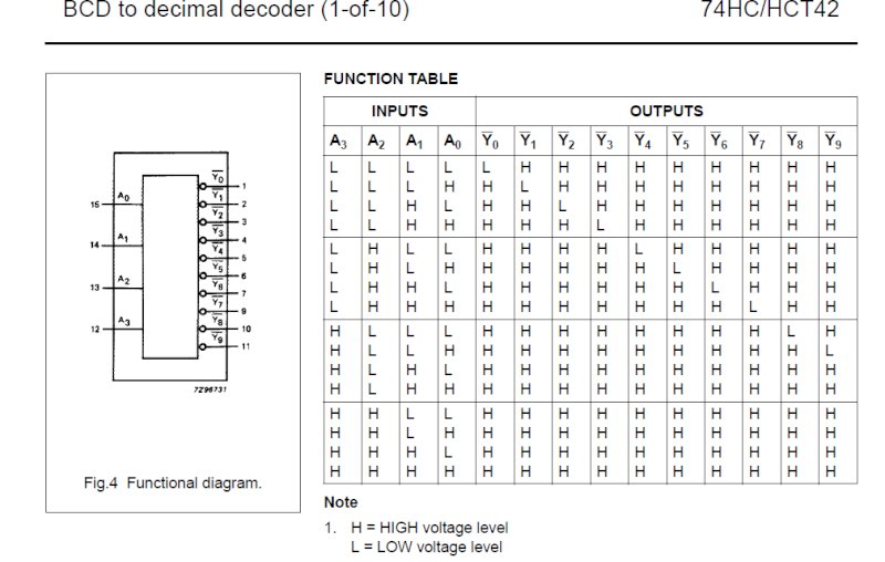
one of many decoding chips is a 7442 ic

which gives us a good output for this purpose   , switching to ground when active

because we have 4 wires going to the selector switch 3 active only we need to tie the "d" (address 3= a3) input to ground to get the correct output logic , which is pretty handy as we can also use this input as the common wire to the switch

heres the 7442 ic  and logic truth table which follows our switches perfectly
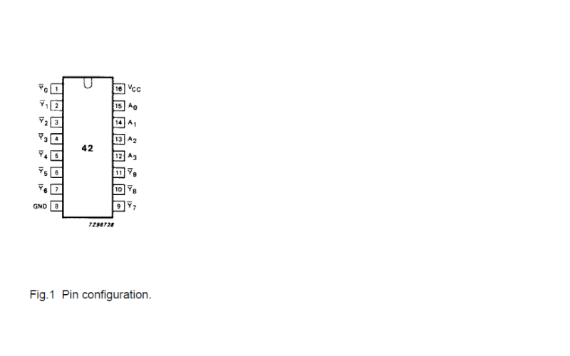
gearshift decoding for aftermarket instruments  7442_p10


gearshift decoding for aftermarket instruments  7442_i11

many have decoded the switching logic of the gear selector indicator switch  and I got - copied sidecar pauls diagrame and truth table
here
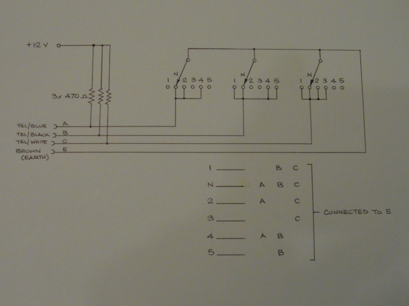
gearshift decoding for aftermarket instruments  Gear_s10


so it lines up just great on the first 3 address pins a0, a1, a2  with a3 tied low


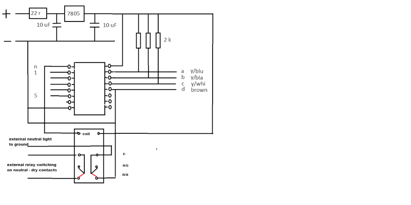
so with that in mind heres my "home made circuit "
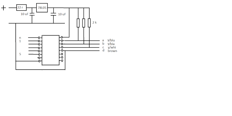
gearshift decoding for aftermarket instruments  Circui11


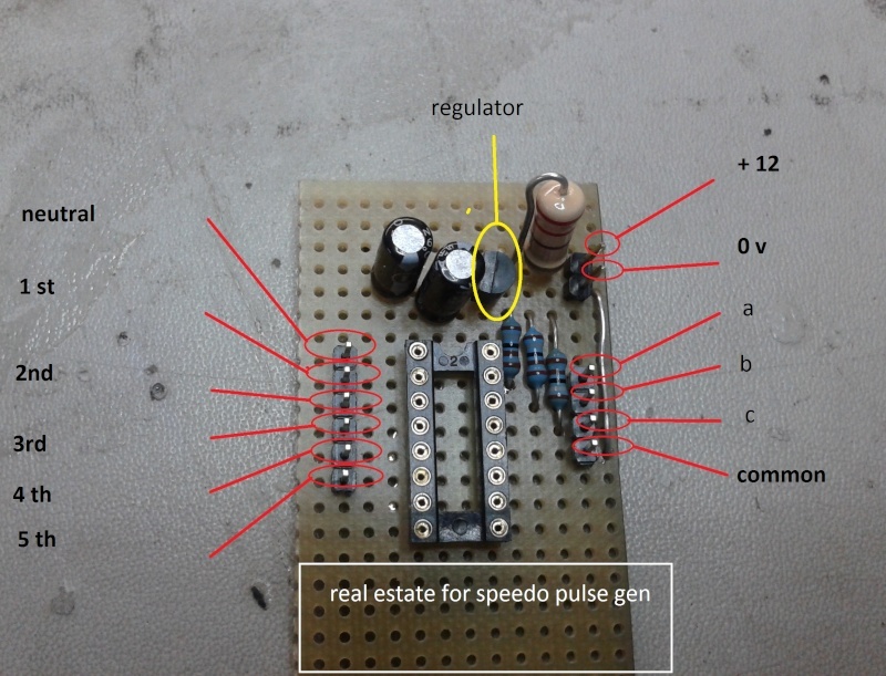
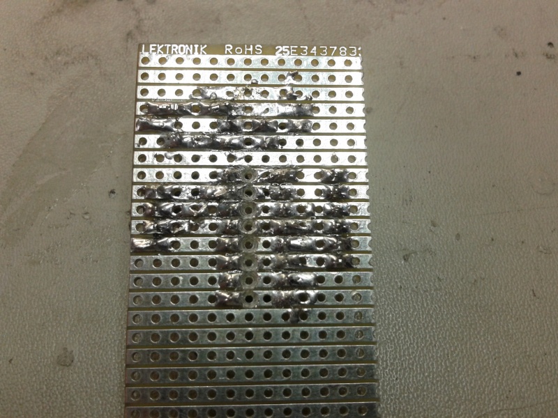
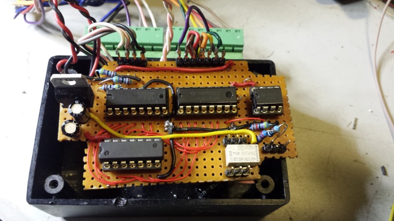
and in physical form

gearshift decoding for aftermarket instruments  Gear_d10

gearshift decoding for aftermarket instruments  2014-021

(psst ..pic taken before some links installed )
I have used pull up resistors from the supply voltage to "wet"  the contacts in the switch (keep them clean) and to provide some reliable switching

whatcha think ?


it should do the job I recon


Last edited by charlie99 on Wed Jul 30, 2014 4:12 pm; edited 1 time in total


__________________________________________________
cheezy grin whilst riding, kinda bloke ....oh the joy !!!! ...... ( brick aviator )

'86 K100 RT..#0090401 ..."Gerty" ( Gertrude Von Clickandshift ) --------O%O
'86 k100 rs.. #######..  "Fred " (f(rame) red ) ( Fredrick leichtundschnell ) - -
bits and pieces from many kind friends across the k100 world ...with many thanks ..
1987 k100rs ########   "Red"  - (red sports rs TWB style )
1989 K100rt #009637   "Black Betty"  (naked rt ala Nigel , now sporting an rs main fairing )
    

GTJos

GTJos
Silver member
Silver member
Very Happy Hi there !
Looks as if you know what you're doing ! Very impressive to me, chapeau mate !! :BW: 

Greetings....

Jos


__________________________________________________
gearshift decoding for aftermarket instruments  Deutch10Ich bin enge Kirchröatsjer jong; adieë wa ?! gearshift decoding for aftermarket instruments  Deutch10
                                1992  K1100LT 6458188
                                1987 K100LT (RS-fairing) 0170844 + sidecar EML GT2001
                                1986 K100RS 0085647 + sidecar Velorex 562
                                1985  K100RT  0027026
    

sidecar paul

sidecar paul
Life time member
Life time member
Good work, Charlie. gearshift decoding for aftermarket instruments  112350 

Nice to have been of some use along the way.

Cheers,
Paul.


__________________________________________________
'84 K100RS (0014643) (owned since '85), 86 K100RS (0018891) with Martello sidecar (built as an outfit in '88),
'51 Vincent (since '67),'72 Montesa Cota (from new), '87 Honda RS125R NF4 (bought 2015) 
....No CARS never ever!
    

robmack

robmack
Life time member
Life time member
Interesting.  Which manufacturer uses separate inputs for gear indication?

You might want to consider substituting a CD4028N for the 74HC42.  First, you can eliminate the LM7805 regulator because the CMOS works directly off the +12V supply.  The output of is only slightly less than the supply voltage, which may be required by the instrument (I ran into this problem on my Motogadgets).  Third, the CMOS has high drive capability, more current than is available in the TTL family.  If you do the substitution, remember to rewire the circuit; the two ICs are functionally equivalent, not pin equivalent.

You probably want to decouple the regulator with a 0.47uF low-ESR cap instead of the 10uF electrolytic you have speced.  It will prevent oscillation of the regulated output.


__________________________________________________
Robert
1987 K75 @k75retro.blogspot.ca
http://k75retro.blogspot.ca/
    

rosskko

rosskko
VIP
VIP
Just to hijack a thread (nice work Charlie) would these gauges fit the bike? 

Plug n play

I don't have the welding soldering skill of Charlie so the less work the better.

I don't really want to fit one of these. Just a question.

gearshift decoding for aftermarket instruments  Instru10


__________________________________________________
1986 K100RT VIN 0093801K100RT with summer fairing for a northern visitor

Basic/2 6308802K100CJ  05/1988

K1100RS 0194321
    

charlie99

charlie99
VIP
VIP
I think he just wants neutral indication rob,  active low .
but good to know about the other stuff eh ?

all good recommendations

the 7442 will sink 85 ma ( or so it says )  all good for a  relay , if need be
as I said, ready to test well see how it goes huh ?


__________________________________________________
cheezy grin whilst riding, kinda bloke ....oh the joy !!!! ...... ( brick aviator )

'86 K100 RT..#0090401 ..."Gerty" ( Gertrude Von Clickandshift ) --------O%O
'86 k100 rs.. #######..  "Fred " (f(rame) red ) ( Fredrick leichtundschnell ) - -
bits and pieces from many kind friends across the k100 world ...with many thanks ..
1987 k100rs ########   "Red"  - (red sports rs TWB style )
1989 K100rt #009637   "Black Betty"  (naked rt ala Nigel , now sporting an rs main fairing )
    

robmack

robmack
Life time member
Life time member
rosskko wrote:Just to hijack a thread (nice work Charlie) would these gauges fit the bike? 
Rosskko,

The gauges you've shown are simple indicators -- oil temp, water temp, boost, tacho. These would be plug-n-play on the K-bikes. You'd need to figure out how to mount them, but electrically they'd work with the signals produced by the sensors to which they are matched. The water temp would need investigation whether the sensor on the bike is in the range of the meter.


__________________________________________________
Robert
1987 K75 @k75retro.blogspot.ca
http://k75retro.blogspot.ca/
    

Rick G

Rick G
admin
admin
The neutral earth needs to work a relay so a start lockout can be incorporated and that needs to be 35-40mA.
Charlie I just sent the info sheet that came with the instrument in a PM.
This is the one I bought.
http://www.ebay.com.au/itm/New-Backlight-LCD-Digital-Motorcycle-Speedometer-Odometer-Bike-Tachometer-/181177839078?pt=AU_Motorcycle_Parts_Accessories&hash=item2a2f0a6de6
I chose it because of the gear indicator and clock and a great big red-line red light.


__________________________________________________
"Man sacrifices his health in order to make money.
Then he sacrifices money to recuperate his health.
And then he is so anxious about the future that he does not enjoy the present; the result being that he does not live in the present or the future; he lives as if he is never going to die, and then dies having never really lived."   Dalai Lama


Bikes 1999 K1100 LT with a Big Block 1200
    

robmack

robmack
Life time member
Life time member
Charlie,  You'll have to figure in the starter relay coil current as well as the neutral light current.  That will amount to about 560 mA of current.
gearshift decoding for aftermarket instruments  Capture
This is a screen shot of my neutral detect circuit simulation running under NI Multisim.  K1 is an electrical simulation of the starter relay based on my electrical measurements; it draws 546 mA.  The EMR171A12 is the neutral light simulation; it draws 11 mA.  Together, about 556 mA.  That will blow your 74HC42 away.  Maybe what is better is what I've done, gone and used a IRF9520 MOSFET as a current booster.  You might also be able to use it as a voltage booster as well so that it outputs a 12V signal instead of 5V TTL.

If you want / need info on the speedo pulse circuit, contact me.  I've worked on several iterations of one design with mixed success.  I'd love to solve my problem with this circuit.  Putting two heads together might work.


Last edited by robmack on Wed Jul 30, 2014 10:06 pm; edited 2 times in total


__________________________________________________
Robert
1987 K75 @k75retro.blogspot.ca
http://k75retro.blogspot.ca/
    

Rick G

Rick G
admin
admin
I was planing using a miniature relay that draws 35mA to feed the starter relay and not try to run it direct because I do like fried chips (fries) but not silicone ones.


__________________________________________________
"Man sacrifices his health in order to make money.
Then he sacrifices money to recuperate his health.
And then he is so anxious about the future that he does not enjoy the present; the result being that he does not live in the present or the future; he lives as if he is never going to die, and then dies having never really lived."   Dalai Lama


Bikes 1999 K1100 LT with a Big Block 1200
    

charlie99

charlie99
VIP
VIP
ditto rick   I had thought of maybe a 2 pole relay , one pole for the indication to the instruments , the other to the other electrikery  of starter etc

didn't seem hard to me ....just wanted to decode the bcd to 1 (or more ) driven circuit that gets us away from other mechanics

hey its all a work in action, and will be fun in the process

for some it might demystify what some of us are thinking electronics wise


__________________________________________________
cheezy grin whilst riding, kinda bloke ....oh the joy !!!! ...... ( brick aviator )

'86 K100 RT..#0090401 ..."Gerty" ( Gertrude Von Clickandshift ) --------O%O
'86 k100 rs.. #######..  "Fred " (f(rame) red ) ( Fredrick leichtundschnell ) - -
bits and pieces from many kind friends across the k100 world ...with many thanks ..
1987 k100rs ########   "Red"  - (red sports rs TWB style )
1989 K100rt #009637   "Black Betty"  (naked rt ala Nigel , now sporting an rs main fairing )
    

bushyintas

bushyintas
Silver member
Silver member
great work Charlie...

A lot smaller than my attempt with mini relays, works but yours would fit almost anywhere, any chance of purchasing the final product?

Regards Bushy.


__________________________________________________
Bushy

k100 RT 1988 #0095723
K100 RT 1984 into Custom Single seat.  #0024503
    

charlie99

charlie99
VIP
VIP

If you want / need info on the speedo pulse circuit, contact me.  I've worked on several iterations of one design with mixed success.  I'd love to solve my problem with this circuit.  Putting two heads together might work.
 
I had thought to use your circuit with the lm358 for the speedo sensor  rob ...(sorry if I got the numbers wrong )

but I have another idea which might be a little simpler, keep the parts count down and be a little more versatile

the basis was to use a darlington npn straight from the speedo sensor (with the right biasing )  and make it an open collector ...I really don't think that amplifying the negative going signal is any advantage ...all we need to do is rely on the positive going signal to turn the trani on, into saturation at each (positive ) pulse  (thus grounding the input to the speedo )

I have an idea that most of the after market stuff works with ground switching on the speedo input , if not using their "specialised " sensor

I don't have one sitting in front of me to experiment ...is an issue ....but at "ricks find" price...  could be worthy of investigating further ?
but as you know my projects list exceeds my financial aspirations ... erm... for the moment  

back to the forks fitment hopefully this weekend ...bugger that I haven't had time to get the new rim to the "passionate tyre guy" for the new speed demon "exchange" fitment


__________________________________________________
cheezy grin whilst riding, kinda bloke ....oh the joy !!!! ...... ( brick aviator )

'86 K100 RT..#0090401 ..."Gerty" ( Gertrude Von Clickandshift ) --------O%O
'86 k100 rs.. #######..  "Fred " (f(rame) red ) ( Fredrick leichtundschnell ) - -
bits and pieces from many kind friends across the k100 world ...with many thanks ..
1987 k100rs ########   "Red"  - (red sports rs TWB style )
1989 K100rt #009637   "Black Betty"  (naked rt ala Nigel , now sporting an rs main fairing )
    

charlie99

charlie99
VIP
VIP
bushyintas wrote:great work Charlie...

A lot smaller than my attempt with mini relays, works but yours would fit almost anywhere, any chance of purchasing the final product?

Regards Bushy.

thanks for the vote of confidence bushy

lets see how things develop eh ?   if I can, it will be , available
or at least a pretty good instruction picture set of how to do it !!!


__________________________________________________
cheezy grin whilst riding, kinda bloke ....oh the joy !!!! ...... ( brick aviator )

'86 K100 RT..#0090401 ..."Gerty" ( Gertrude Von Clickandshift ) --------O%O
'86 k100 rs.. #######..  "Fred " (f(rame) red ) ( Fredrick leichtundschnell ) - -
bits and pieces from many kind friends across the k100 world ...with many thanks ..
1987 k100rs ########   "Red"  - (red sports rs TWB style )
1989 K100rt #009637   "Black Betty"  (naked rt ala Nigel , now sporting an rs main fairing )
    

bushyintas

bushyintas
Silver member
Silver member
thanks Charlie,

Look forward to seeing your progress.


__________________________________________________
Bushy

k100 RT 1988 #0095723
K100 RT 1984 into Custom Single seat.  #0024503
    

Finnigan

Finnigan
Silver member
Silver member
Did this mod successfully with 3 larger automotive relays, the only issue is shoving the bundle into the space under the tank and losing connection.  Might try the smaller relays on a board


__________________________________________________
1990 k100LT
    

Rick G

Rick G
admin
admin
Finnigan wrote:Did this mod successfully with 3 larger automotive relays, the only issue is shoving the bundle into the space under the tank and losing connection.  Might try the smaller relays on a board
That is just for the neutral light, Charlie is working on a decoder or recoder so that I will have a gear counter showing 1 N 2 3 4 5 on the new instrument panel.


__________________________________________________
"Man sacrifices his health in order to make money.
Then he sacrifices money to recuperate his health.
And then he is so anxious about the future that he does not enjoy the present; the result being that he does not live in the present or the future; he lives as if he is never going to die, and then dies having never really lived."   Dalai Lama


Bikes 1999 K1100 LT with a Big Block 1200
    

Finnigan

Finnigan
Silver member
Silver member
That would be nice, I'm still working on 'teaching' my dashboard gears.  I think its just a ratio of speed and revs


__________________________________________________
1990 k100LT
    

charlie99

charlie99
VIP
VIP
just an update

nearly finished the decoder to ricks gauge

haven't worked on the speedo trigger as of yet but have some parts to play with ...just need a speedo sensor to test what I have in mind  and I guess eventually a gauge to test it out on  -- have a couple of connections for input and output already as spares for the connections

I have added a relay with dry contacts for external things (power relay stuff and diode feed ?) ...and the other side (double throw double pole contacts ) to ground out the led in the instruments @ 12 volts measured by rick  neutral  indicator led ?

but in a box at least
gearshift decoding for aftermarket instruments  20150112


and an updated circuit to what I think will suit ricks requirements for that gauge

gearshift decoding for aftermarket instruments  Circui10
 

its taken a while with all the things happening lately


__________________________________________________
cheezy grin whilst riding, kinda bloke ....oh the joy !!!! ...... ( brick aviator )

'86 K100 RT..#0090401 ..."Gerty" ( Gertrude Von Clickandshift ) --------O%O
'86 k100 rs.. #######..  "Fred " (f(rame) red ) ( Fredrick leichtundschnell ) - -
bits and pieces from many kind friends across the k100 world ...with many thanks ..
1987 k100rs ########   "Red"  - (red sports rs TWB style )
1989 K100rt #009637   "Black Betty"  (naked rt ala Nigel , now sporting an rs main fairing )
    

charlie99

charlie99
VIP
VIP
just an update

did some work at figuring out the gauges bit on ricks new instruments


along the way have destroyed the decoder ic (lucky I made it socketed ) ....as the gear selection draws about 70-90 milli amps (about .1 amp) on each leg of the gear indication of the speedo to operate ....the ic max is 25 milliamp .025 a   ...I had assumed it would only be a logic level requirement to switch the gear change indicator .


I have another ic or two ...but will have to build into it a buffer (uln2003 ) or something to handle the extra current .
the good news is the neutral lamp only draws about 8 milliamp .so can drive it straight from the ic ....but will incorporate it to the buffer chip ..may still  have to incorporate the relay ....ill have a look around and see what I can do for the enable start operation  for about 1 amp but add a current limit to it so it cant overload the indicator decoder electronics .


__________________________________________________
cheezy grin whilst riding, kinda bloke ....oh the joy !!!! ...... ( brick aviator )

'86 K100 RT..#0090401 ..."Gerty" ( Gertrude Von Clickandshift ) --------O%O
'86 k100 rs.. #######..  "Fred " (f(rame) red ) ( Fredrick leichtundschnell ) - -
bits and pieces from many kind friends across the k100 world ...with many thanks ..
1987 k100rs ########   "Red"  - (red sports rs TWB style )
1989 K100rt #009637   "Black Betty"  (naked rt ala Nigel , now sporting an rs main fairing )
    

Rick G

Rick G
admin
admin
Great work Chas I am looking forward to having Chookie on the road with all the new whistles.


__________________________________________________
"Man sacrifices his health in order to make money.
Then he sacrifices money to recuperate his health.
And then he is so anxious about the future that he does not enjoy the present; the result being that he does not live in the present or the future; he lives as if he is never going to die, and then dies having never really lived."   Dalai Lama


Bikes 1999 K1100 LT with a Big Block 1200
    

robmack

robmack
Life time member
Life time member
charlie99 wrote:
along the way have destroyed the decoder ic (lucky I made it socketed ) ....as the gear selection draws about 70-90 milli amps (about .1 amp) on each leg of the gear indication of the speedo to operate ....the ic max is 25 milliamp .025 a   ...I had assumed it would only be a logic level requirement to switch the gear change indicator .

Don't get this Charlie.  The input to the decoder input stage will sink whatever current it needs either from +5V through the pull-up resistors when the TGPI is open circuit, or source whatever current is demanded to ground when the TGPI is engaged.  What is drawing 70mA, causing the overload?  I'm not clear on your description possibly; maybe you're talking the output stage.

Ok Ok, after rereading the description a couple times, my syrup-for-brains finally got it The output to the gear indicators are drawing too much current, causing the IC failure. Using a high current buffer stage after the decoder will boost the output and remedy the situation. That's exactly what I found out I needed to do on my circuit.

 
I have another ic or two ...but will have to build into it a buffer (uln2003 ) or something to handle the extra current .

Good luck with the uln2003.  I tried that IC on my design but it switched too fast causing flickering in the LED display.  I chose a MMPQ2222 quad transistor array as output drivers on my newest design.  They are just open collector drivers that switch to ground when driven high (through a 10K base resistor).


Last edited by robmack on Mon May 04, 2015 9:28 pm; edited 1 time in total


__________________________________________________
Robert
1987 K75 @k75retro.blogspot.ca
http://k75retro.blogspot.ca/
    

Two Wheels Better

Two Wheels Better
Moderator
Moderator
This is all very interesting to me simply because I have had to sort some form of instruments out for the BB project. In the end I decided that I don't need a tacho, a short rack of idiot lights will suffice for the various warning lamps (blinkers, charging, high beam, and that's about it).

I don't need to know what gear I'm in, including neutral, the fuel level is just a pop of the cap away, and if the fan doesn't come on and there's a mass of steam about I reckon she must be overheating.

So I chose a simple mechanical speedo with odo and tripmetre and am fabricating another axle for an R1150RT wheel with the speedo drive gear off the left hand side (yes, I've worked out how to hold the speedo drive cog in place so it doesn't go all whirly on me as I move forward).

If it goes pear-shaped then I'll be back here and there sussing out what LED/LCD digital electro wham bangy I might be able to use. I was checking out Spiegler USA and the Motogadget site and them M Units and M Buttons sure enough look good. I could rid the bike of another ten pounds of wiring loom.

Let us know how it goes, Chazza and Rick! I can't wait to see El Gallo (The Chook).


__________________________________________________
"A long ride is the answer to a question you will soon forget!" ~ Anonymous
1977 R75/7-100, '93 K11/K12 Big Block, '93 K1100RS, '95 R100 Mystic, '96 K1100RS, 2 x '98 K1200RS, '06 K1200R & '09 K1300GT
    

charlie99

charlie99
VIP
VIP
been looking at some other options too rob

the uln2003 was the first thing that came to mind ...as an output driver

think I have found something with pnp and npn pairs that may just follow the logic closely

yes I was immensely surprised at the gear indicator input current requirement ....il guess that the normal (is there such a thing ) input could be just a switch mechanism with 6 or so outputs and a rotating armature as a common ?

was hoping that I could use one of the darlingtons in the uln for the speedo pulse generation ...lets see what happens eh ?!!


__________________________________________________
cheezy grin whilst riding, kinda bloke ....oh the joy !!!! ...... ( brick aviator )

'86 K100 RT..#0090401 ..."Gerty" ( Gertrude Von Clickandshift ) --------O%O
'86 k100 rs.. #######..  "Fred " (f(rame) red ) ( Fredrick leichtundschnell ) - -
bits and pieces from many kind friends across the k100 world ...with many thanks ..
1987 k100rs ########   "Red"  - (red sports rs TWB style )
1989 K100rt #009637   "Black Betty"  (naked rt ala Nigel , now sporting an rs main fairing )
    

Two Wheels Better

Two Wheels Better
Moderator
Moderator
I for one applaud you guys for your efforts here. It is a rare language that you speak but it's a heap of fun reading as you toss the terms and tech speak about so easily. I confess to not having a bright bulb when it comes to the dark art of micro electricity conveyance, same goes for the intricacies of 'puters - bloody things give me my daily frust-ration, but I have to use 'em! 
Wink

By the looks of the many digital gauges adorning various kafé bikes and kustoms on the forum you are having an impact and making it easier for folk to set them up. Cheers.


__________________________________________________
"A long ride is the answer to a question you will soon forget!" ~ Anonymous
1977 R75/7-100, '93 K11/K12 Big Block, '93 K1100RS, '95 R100 Mystic, '96 K1100RS, 2 x '98 K1200RS, '06 K1200R & '09 K1300GT
    

charlie99

charlie99
VIP
VIP
think I got it sused at last

time is the thing ...and I never have enough

heres hopefully a link to a test setup that will function correctly at last

blew up a few components during the last iteration

now using a logic inverter and a uln2003 open collector driver chip for ricks 100 ma current to instruments
and added a relay for dry contacts out to the system .

Plus the speedo signal amplifier circuit ...that I will be putting through the driver chip for pulses to the instruments - speedo

draws about 23ma  with one output active (about 0.023 amps)


https://www.youtube.com/watch?v=VNNieq544Po&feature=youtu.be


sorry was marked private ...made public now


__________________________________________________
cheezy grin whilst riding, kinda bloke ....oh the joy !!!! ...... ( brick aviator )

'86 K100 RT..#0090401 ..."Gerty" ( Gertrude Von Clickandshift ) --------O%O
'86 k100 rs.. #######..  "Fred " (f(rame) red ) ( Fredrick leichtundschnell ) - -
bits and pieces from many kind friends across the k100 world ...with many thanks ..
1987 k100rs ########   "Red"  - (red sports rs TWB style )
1989 K100rt #009637   "Black Betty"  (naked rt ala Nigel , now sporting an rs main fairing )
    

Two Wheels Better

Two Wheels Better
Moderator
Moderator
Mad scientists at work. Love it.


__________________________________________________
"A long ride is the answer to a question you will soon forget!" ~ Anonymous
1977 R75/7-100, '93 K11/K12 Big Block, '93 K1100RS, '95 R100 Mystic, '96 K1100RS, 2 x '98 K1200RS, '06 K1200R & '09 K1300GT
    

charlie99

charlie99
VIP
VIP
finally finished it and have it working to the instruments

had to use an inverter to reverse the logic to the open collector driver ic  (uln 2003 ) which has 7 outputs worthy of using

outputs 1 to 6 are for the various gear position functions and output 7 I have incorporated to a preamplifier the drives the 7th output
in this case  emulates a reed switch mounted on the forks (or somewhere ) that pulses when a magnet zips past nearby .

so what it does, is pulses the speedo input with a grounding effect  like a reed switch would .

the neutral position output activates a double pole double throw relay ...so as to give the instruments an indication of neutral   and a set of dry contacts for external ignition starting purposes ...

heres the final hooked up and working gear display ....(should have got a speedo observation as well ) but alas it has gone to a well deserved home

https://www.youtube.com/watch?v=ZJmh2j44jrM&feature=youtu.be

block diagram

gearshift decoding for aftermarket instruments  Block_10

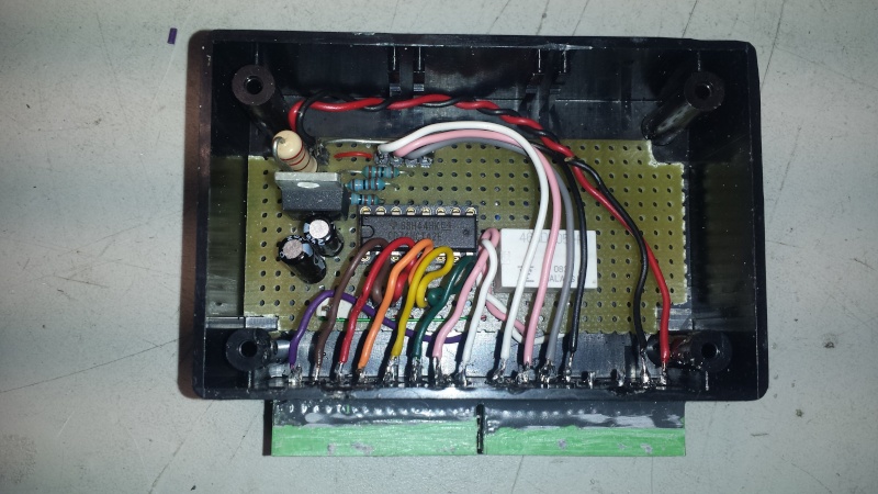
and pic of the almost finished item ,,before being coated with some conformal coating and being packed away snugly in a plastic box

gearshift decoding for aftermarket instruments  20160412


__________________________________________________
cheezy grin whilst riding, kinda bloke ....oh the joy !!!! ...... ( brick aviator )

'86 K100 RT..#0090401 ..."Gerty" ( Gertrude Von Clickandshift ) --------O%O
'86 k100 rs.. #######..  "Fred " (f(rame) red ) ( Fredrick leichtundschnell ) - -
bits and pieces from many kind friends across the k100 world ...with many thanks ..
1987 k100rs ########   "Red"  - (red sports rs TWB style )
1989 K100rt #009637   "Black Betty"  (naked rt ala Nigel , now sporting an rs main fairing )
    

Motorbike Mike

Motorbike Mike
Life time member
Life time member
All of the above is indeed very clever and I'm sure that I couldn't have come up with that solution and that's why I had to use something much simpler.
Over a year ago I used a slightly modified R1100 neutral switch. It only has the one contact point and all I had to do was move the detent on the wheel to suit the neutral position the K gearbox uses. Sadly I don't have any images as the switch is in the back of the gearbox and no matter how much I enjoy this forum, I'm not taking it out-so there!

Seriously though, it is worth a look at the R1100 switch. Very Happy


Last edited by Motorbike Mike on Mon Apr 25, 2016 12:27 pm; edited 1 time in total


charlie99

charlie99
VIP
VIP
gearshift decoding for aftermarket instruments  112350


__________________________________________________
cheezy grin whilst riding, kinda bloke ....oh the joy !!!! ...... ( brick aviator )

'86 K100 RT..#0090401 ..."Gerty" ( Gertrude Von Clickandshift ) --------O%O
'86 k100 rs.. #######..  "Fred " (f(rame) red ) ( Fredrick leichtundschnell ) - -
bits and pieces from many kind friends across the k100 world ...with many thanks ..
1987 k100rs ########   "Red"  - (red sports rs TWB style )
1989 K100rt #009637   "Black Betty"  (naked rt ala Nigel , now sporting an rs main fairing )
    

31Back to top Go down   gearshift decoding for aftermarket instruments  Empty R1100 Neutral Switch Sun Jun 12, 2016 3:37 am

Kai Ju

Kai Ju
active member
active member
Thanks for the tip about the R1100 neutral switch.
I have to admit the simplicity of a simple grounding switch is far more appealing than a black box or mini relays, especially since all I need/want is a neutral light.
I assume it is necessary to seal the back of the switch where the gear position switch would ordinarily close it off. Or is the oil seal for the shift drum shaft enough ?
Interesting to see that BMW used a potted micro switch to fashion a neutral switch.


32Back to top Go down   gearshift decoding for aftermarket instruments  Empty wiring diagram Thu Jul 27, 2017 3:36 am

maz_dede

maz_dede
active member
active member
may i know wiring diagram for your last design. i need this for my K75


MD K100RS

MD K100RS
active member
active member
Very impressive - I wouldn't know where to begin!!studystudystudy

http://www.ars-natura.com
    

charlie99

charlie99
VIP
VIP
Ill post an update and full 'as finished' circuit soon


__________________________________________________
cheezy grin whilst riding, kinda bloke ....oh the joy !!!! ...... ( brick aviator )

'86 K100 RT..#0090401 ..."Gerty" ( Gertrude Von Clickandshift ) --------O%O
'86 k100 rs.. #######..  "Fred " (f(rame) red ) ( Fredrick leichtundschnell ) - -
bits and pieces from many kind friends across the k100 world ...with many thanks ..
1987 k100rs ########   "Red"  - (red sports rs TWB style )
1989 K100rt #009637   "Black Betty"  (naked rt ala Nigel , now sporting an rs main fairing )
    

maz_dede

maz_dede
active member
active member
charlie99 wrote:Ill post an update and full 'as finished' circuit soon
i will waiting for final result bro..


Sponsored content


View previous topic View next topic Back to top  Message [Page 1 of 1]

Permissions in this forum:
You cannot reply to topics in this forum