BMW K bikes (Bricks)


You are not connected. Please login or register

Go to page : Previous  1, 2

View previous topic View next topic Go down  Message [Page 2 of 2]


51Back to top Go down   Flowmeter restoration - Page 2 Empty Re: Flowmeter restoration Tue Apr 05, 2016 8:32 pm

K75cster


Life time member
Life time member
Beamer wrote:
I attached a fine nylon thread to the rear arm of the rotor and loaded it progressively using water and a syringe. One cc of water is a gram and that allows adjusting the load and calculating the torque.

As before I normalised the voltage by dividing by the test voltage so the result is generalised.

Flowmeter restoration - Page 2 Debi_t11

G'day Beamer, I'm having trouble understanding the nylon thread, how did you load that thread with 1cc of water?

I like the idea of being able to match or index off the cog points that is a great way to align and match the voltage percentage.
One day when people write in and say they think its a bit fuelly in the bottom rev range, or a bit of an hesitation on opening the throttle, they will have something to check.


52Back to top Go down   Flowmeter restoration - Page 2 Empty Re: Flowmeter restoration Tue Apr 05, 2016 9:38 pm

Beamer

Beamer
Platinum member
Platinum member
OK, I didn't detail that well enough to reproduce it.

There are two separate things being done here. This initial test using the teeth to compare angular displacement of the vane to output voltage and the second test meauring the torque on the spring to output voltage. So the second did not use the teeth and did not measure angles.

The thread was attached to the back of the plate holding the wiper and a container to hold water. The container weighed 26g , less than the initial force to open the vane from the closed position. The thread was passed over a pulley wheel on the edge of the bench to ensure free movement and the container suspended vertically.

Water was then added 0.5 cm^3 at a time using a syringe and output voltage monitored. The weight of the container and water and the radial distance of the point of attachment is used to calculate the torque. That is the graphs shown above.

It is necessary to rotate the body of the flow meter from time to time to keep the thread nearly perpendicular to the radius to the point of attachment to ensure that torque is equal to the tension in the thread times the radius. This movement can be seen where there are two points close to each other with the same torque value. The difference in these values can be seen to be small and thus the torque is accurate enough using this method.


https://i.servimg.com/u/f86/19/45/29/82/debi_m13.png

There were small, occasional variations in the power supply I was using ( of the order of 10-20mV ). This could be improved but was not really significant.

I now have a measurement method that can assess the effect of moving the spring and can detect the start of output regulation. This method should be accessible to anyone with a DVM and a 12V battery. ( The battery would be more stable but I preferred the PSU which has over current protection if anything moves and shorts out.).

I hope that makes it clearer how this was done. Thanks for your interest.


Last edited by Beamer on Wed Apr 06, 2016 4:42 pm; edited 2 times in total


53Back to top Go down   Flowmeter restoration - Page 2 Empty Re: Flowmeter restoration Tue Apr 05, 2016 9:50 pm

Beamer

Beamer
Platinum member
Platinum member
Several people recommend moving the plate or bending the wiper arm contacts to get a clear track for the pot. This is a good idea after 20y of wearing a groove but does imply resetting the start position. It can be set to the corner of the first resistor but this does not specify it accurately .


I think there is a need to find the proper initial conditions for this.

I do not favour bending the copper arm since this will almost certainly result in either too much or too little contact pressure. These are precision instruments and should be respected if they are to remain precise and to ensure them a long and happy life. Very Happy


54Back to top Go down   Flowmeter restoration - Page 2 Empty Re: Flowmeter restoration Wed Apr 06, 2016 10:15 pm

Beamer

Beamer
Platinum member
Platinum member
OK, I pulled the AFM of the K75. This bike has relatively low mileage ( but it's still 20+ years old ). The unit is in pretty good condition. I'll have to take this as my reference for the moment.

I does have a couple of mm movement at the barn door before the pot. moves off the deck. I'm starting to conclude this is a valid adjustment to infill the rather large jumps in the teeth of the spring setting.

A spring adjustment acts to move my x-axis ; the wiper zero adjustment shifts the y-axis. The latter will introduce a slight non-linearity but can bring the curve nearer to the ideal than just relying on whole teeth jumps which are quite crude.

I now have the replacement unit for the damaged one on the k100 pretty close to the good unit of the K75.


This is about all I can do without a gas analyser and / or a proper BMW calibration procedure.

Anyway, at least I have developed a test procedure, gained some understanding of how these things work and got an unknown second hand unit tuned up close to a known good one.

That's a start. Very Happy


Flowmeter restoration - Page 2 Debi_t15


55Back to top Go down   Flowmeter restoration - Page 2 Empty Re: Flowmeter restoration Thu Apr 07, 2016 12:52 am

rawdonball

rawdonball
Gold member
Gold member
I think this might be a useful thread for me one day, if I read it enough times to understand / follow what's being talked about! Electronics is mostly a black box for me.

Am I right in thinking that spring 'fatigue' in the form of plastic deformation / permanent set, can be tuned out by adjustment? In other words, is it a change in spring rate which is of concern in that it will impact the desired linear relationship between fuel delivery and mass of intake air?

It would be interesting to compare the slopes of the graphs (paper or electronic!) for new and old springs when angular deflection is plotted against applied torque per Beamer's ingenious apparatus. Good work Mate - I wish you the best in your up hill battle in smoothing over some ruffled feathers...


__________________________________________________
'88 K100RT, '86 K75C, '05 Yamaha TTR250
    

56Back to top Go down   Flowmeter restoration - Page 2 Empty Re: Flowmeter restoration Thu Apr 07, 2016 3:32 am

Beamer

Beamer
Platinum member
Platinum member
Flowmeter restoration - Page 2 Debi_t17

My expertise in materials science is limited. However, as I understand it a spring under load will, if anything, just take a permanent set rather than the physical properties ( elastic constant ) of the metal changing.

If this is the case, it is just necessary to add a little more pre-load to the spring. This will be achieved by tightening by a tooth or two. 

Since I only have 20 year old units to compare, and no data, I don't know whether this is happening, though on a multi turn spring with about 54 teeth per turn on the adjuster, it would not take much change to equal one tooth. These are very sensitive instruments.


One thing that does need setting is the position of the wiper if the unit is disturbed to find a clean track when the carbon gets worn. This seems to be typical in many units with the substantial mileage most of these bikes now have.

The above graph is exactly the same data as the previous one, presented as a line graph. It can be seen that there is a slightly different curvature. I think this is due to a small difference in the spring strengths. The more curved one being weaker spring.

The graph I showed earlier, with modified unit, shows some quite bad irregularities. These may be either track damage or dirt or wear is the mechanics of the vane which may be solved by a complete strip down. However, in view of the number and price of second hand units, replacement probably makes more sense.

This kind of condition would not be revealed by a simple external test. It requires the kind of graduated load test I've done here.

see previous comments on use of gnuplot to produce graphs. Here I'm plotting the 8th and 6th sets of results in my data file ( the index thing ).


Code:
set title "Bosch flow meter: torque test"
set xlab "spring load / N.cm "
set ylab "noramlised potentiometer wiper voltage"
set key top left Left reverse

vref=6.01; rad= 27.4e-3; g=9.81
# column 1 spring load data in cm^3 of water ie grams; add empty contain weight: 26g

plot "torque_test.dat" using (($1+26)*g*rad/10.):($2/vref) index 8 with lines title "K75 unit" , "" using (($1+26)*g*rad)/10.):($2/vref) index 6 with lines title "untampered"


Last edited by Beamer on Fri Apr 08, 2016 5:47 pm; edited 8 times in total


57Back to top Go down   Flowmeter restoration - Page 2 Empty Re: Flowmeter restoration Thu Apr 07, 2016 1:47 pm

robmack

robmack
Life time member
Life time member
Very useful investigation Beamer and thank you. It would be nice if you could post up a procedure and accompany it with photos of the test setup so that others can duplicate your methodology. I think there is a lack of understanding as to how to rig up the think string and syringe, how to orient the unit for testing, how to hook up electrical test equipment and how to adjust the resistor board to expose a clean track to the wiper.


__________________________________________________
Robert
1987 K75 @k75retro.blogspot.ca
http://k75retro.blogspot.ca/
    

58Back to top Go down   Flowmeter restoration - Page 2 Empty Re: Flowmeter restoration Thu Apr 07, 2016 2:18 pm

Beamer

Beamer
Platinum member
Platinum member
I took some photos of the test rig but they are not the best.  I've just bought another unit to test,  so I'll try to get some clearer shots.

I think I covered the wiring connections but maybe it all needs condensing down. This is getting a bit long, and details are a bit spread out with other comments.

I've been doing some test riding this arvo and having tested the two working units they seem best on the original notch but I did make quite a lot of change on the idle mixture and can now set the timing correctly. It's already a different bike.

With one unit it seems to have a nice little push between 4 and 6 thousand. That's great but since these motors should have a flat response curve that suggests it is not quite right at low and higher revs. I think I'm seeing the difference in the two curves I plotted above. Also I had to screw the mixture screw right down ( rich end ) which probably means it not right anyway.

The plug colour still looks a little rich, but I took it back notch and thought it ran well it was a lot less fun. That would probably do as an economy setting. No sign of detonation but it was not as responsive. I'll put the original K75 unit back on tomorrow and do some more tests.

The torque test has been informative and increased understanding but I don't feel I have a : do this; test this and adjust this solution yet. The main thing I want to suss is how to set the wiper position after disturbing the board. There is a good reason to move the board and get a clean track but this raises the need to reset the wiper. Sadly, we don't know the offical procedure here.

Maybe I will be able to device a method to determining that. I already have a test method which is the first step.

Quick reply on moving the board, I just elongated the mounting holes and pushed to support plate closer to the casting. It only need about 1mm to get a clean track. That's described above too. I'll right a resume when I'm done.


59Back to top Go down   Flowmeter restoration - Page 2 Empty Re: Flowmeter restoration Fri Apr 08, 2016 2:29 am

K75cster

K75cster
Life time member
Life time member
Thanks Beamer, I get it now, when testing torque the arm would ideally sweep at 1/4 to or 1/4 past the hour any time it swings near 20to or 20 past it would require a reset. A perfectly simple way to test. I like it, and think I could repeat it if I need to be sure of things, certainly if I suspected the flap of impeding the proper working of the bike. As you say knowing what it puts out and what it should put out is critical to understanding if it need a rebuild or when to buy another one.


__________________________________________________
Keith - 1987 K75c with r100rt replica fairing and half of a 1984 K100rt 1992 K1100LT a blue one

The Clever are adept at extricating themselves from situations that the wise would have avoided from the outset - QUOTE from david Hillel in Out of the Earth.
    

60Back to top Go down   Flowmeter restoration - Page 2 Empty Re: Flowmeter restoration Fri Apr 08, 2016 5:22 am

Beamer

Beamer
Platinum member
Platinum member
Someone posted a graph done measuring the distance to the edge of vane and applying the test voltage. ( post seems to have been deleted. )

This is good first step since it can be done without breaking the seal on the lid. This is a valid way to see whether the track has been badly damaged and the signal is jumping around unreliably. I think that is the most that can be done from the outside but can be a useful indication whether an intervention is needed. That would be a good addition to the troubleshooting guide.


Unfortunately, passing that test does not mean all is well. So it can reveal a problem but passing that test is not a confirmation that all is well and the meter is in good condition. For example, it will not reveal whether there are tight spots in the mechanics of the vane movement which could lead to serious non-linearities and bad injection performance. For that we need to measure the force applied. That could potentially be done from the outside too by attaching my setup to the vane. ( It would be non linear but could provide a test of a smooth movement: the second thing to establish ).


I have just acquired another unit, which is in pretty poor condition. It's degraded inside around the laser cuts in the resistors. They've gone all furry.It is corroded outside too so I think it must have been stored badly for years, outside the protection of the air box. These things are typically very clean even after 20y since they are well protected and down wind of the air filter. It is interesting since this one is a 1989 model which has a factory mod. to add a fixed wire connection around all the point contacts. It seems that they recognised a reliability problem here. I'd seen a post somewhere where a guy had done a home-made version of the factory mod. I'll post a photo of the mod. later.


I have just edited earlier posts and  added some code to produce the graphs using free gnuplot plotting software, check those posts for details. That code  shows how the torque calculation is done too. Go back to my first graph on page 1 for some quick comments on using gnuplot, a link and my initial data file.


61Back to top Go down   Flowmeter restoration - Page 2 Empty Re: Flowmeter restoration Sat Apr 09, 2016 8:46 am

rawdonball

rawdonball
Gold member
Gold member
You've unearthed some good stuff by the sound of it - I might just be brave enough to crack one open soon.

Thanks


__________________________________________________
'88 K100RT, '86 K75C, '05 Yamaha TTR250
    

62Back to top Go down   Flowmeter restoration - Page 2 Empty Re: Flowmeter restoration Sat Apr 09, 2016 10:29 am

Beamer

Beamer
Platinum member
Platinum member
I want to get to the bottom of setting the wiper position with the vane closed. As I said above, this is like shifting the y axis on my graphs. the spring tension shifts x.

The toothed adjustments of the spring is rather course and I suspect that a little dead zone ( vane moves without changes output voltage ) may be used by Bosch as a means of fine tuning between teeth.

One can visualise that while not identical a vertical shift could be used to align the curves in between two jumps on the gear wheel position.Then the mixture screw fine tunes the tick-over mixture.

If we are to start messing with moving the plate to get a clean track we need to understand this.

My "good" unit on the K75 has quite a bit of dead zone. Unless I'm mistaken, this must have been set that way in the factory ( I'm fairly sure this one had never been opened previously). 

Now, the spare unit I've been fiddling with has slightly more rounded curve to it. This must mean that all springs are not born equal. Manufacturing tolerance. This one is a bit more responsive in mid regime and I think I may keep it and replace the original. I'm supposed to be seeing a garage next week so we can do some gas analysis checks.

OK , here is the effect of the dead-zone. The spare unit had quite a bit of movement before the resistance got off the ground and the output changed. I adjusted out that play so that the output moved almost  as soon as the vane started moving. Obviously this is the same torque since the spring has not been moved.


https://i.servimg.com/u/f86/19/45/29/82/debi_t19.pngFlowmeter restoration - Page 2 Debi_t19
Flowmeter restoration - Page 2 Debi_t20

It can be seen that the effect is quite similar to shifting a tooth  in the richening direction. It seems that this can be used to interpolate between the larger increments of the toothed adjustment on the spring.

I think this should solve the fact that I had to push the idle mixture screw all the way home before, the idla was clearly too weak. Hopefully this will give a snappier throttle response from tick-over, now. Road tests tomorrow.


63Back to top Go down   Flowmeter restoration - Page 2 Empty Re: Flowmeter restoration Sat Apr 09, 2016 3:54 pm

Beamer

Beamer
Platinum member
Platinum member
For those requesting some detail on how this test is being done, this should help visualise what is going on.

The load is applied using a measured amount of water ( adding 2.5 ml at each step ). The recipient weighs 26g, which is less than the load needed to move the vane off the end stop.  A nice smooth pulley wheel ensures minimal resistance so as not to bias the readings.

Flowmeter restoration - Page 2 Boscha12

Bench-top power supply connected to pins 5 and 8 on the AFM. Output voltage measured on the wiper contact arm. Calibrated syringe to dispense the water to load the spring. A test voltage of 6.0V was used to be similar to running conditions. This not critical but should be stable.

Flowmeter restoration - Page 2 Boscha10

Here we see the nylon thread connected to the lug on the back of wiper mechanism. The body of the AFM is clamped so that it can be rotated to maintain approx 90 degrees between the thread and the radius to the point of attachment, as the wiper moves round under load.

Flowmeter restoration - Page 2 Boscha11


64Back to top Go down   Flowmeter restoration - Page 2 Empty Re: Flowmeter restoration Sat Apr 09, 2016 9:17 pm

K75cster

K75cster
Life time member
Life time member
Now that is much clearer, I had envisioned a white plastic thread sticking up from the central pivot pin the flap pivoted on. With a little arm off it of equal length to the flap. Way off the mark was I. Makes much better sense to take the readings from the wiper as that is the torque figure that can define the spring. Thanks, I can re-read and ingest again.


__________________________________________________
Keith - 1987 K75c with r100rt replica fairing and half of a 1984 K100rt 1992 K1100LT a blue one

The Clever are adept at extricating themselves from situations that the wise would have avoided from the outset - QUOTE from david Hillel in Out of the Earth.
    

65Back to top Go down   Flowmeter restoration - Page 2 Empty Re: Flowmeter restoration Sat Apr 09, 2016 10:54 pm

Holister

Holister
Life time member
Life time member
Interesting read Beamer. The photos bring it all together. Thanks.
I'll be taking a bit of a recky into my AFM shortly when my old girl comes off the road for a little TLC.
Cheers


__________________________________________________

1989 K100RT     VIN  0097367 (naked)  
1996 K1100RS   VIN  0451808
 Flowmeter restoration - Page 2 Austra12    Fuel:  95 Octane
Engine Oil: Nulon Full Synthetic 15W50
Gear Box Oil:  Nulon Synthetic 75W90
    

66Back to top Go down   Flowmeter restoration - Page 2 Empty Re: Flowmeter restoration Sun Apr 10, 2016 1:28 pm

Beamer

Beamer
Platinum member
Platinum member
OK, after some more adjustments and road tests I've got this spare flow meter set up real nice.

In 1st and 2nd gear, cutting the throttle and opening up again is really smooth and without hesitation. That was one of faults I'd noted before that I was hoping to fix. Good result there.

Having taken it down to zero dead zone , ie. output moves as soon as the vane moves. performance was not optimal. Plug tests were running a little darker and mid range power was a little less. Not by much but enough to be felt pulling hard up hill.

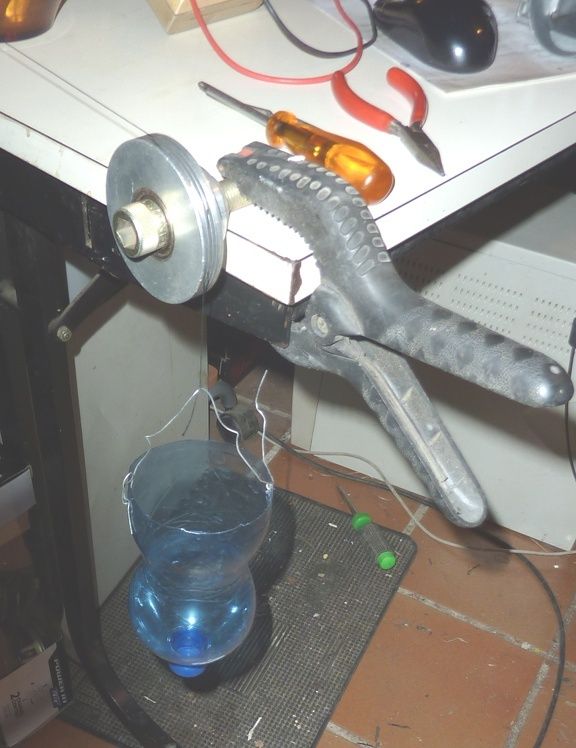
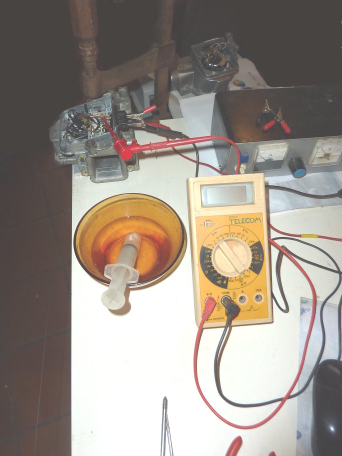
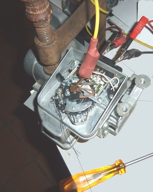
It's difficult to set the wiper accurately since once the lock screw is loosened it tends to jump all over. It needs a bit of trial and error, using the torque test to quantify the torque position where the output starts to move.

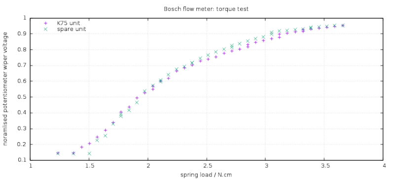
The fourth line on the graph is where I had tested with two notches more tension on the spring. This adds some context to the effect of zero point adjustments. I did not find even a single notch in either direction to be better. One notch weaker ran well but did give a little less power. This may be an option as an economy tuning, subject to checking on a gas analyser that it is not running dangerously weak.

Flowmeter restoration - Page 2 Debi_t21
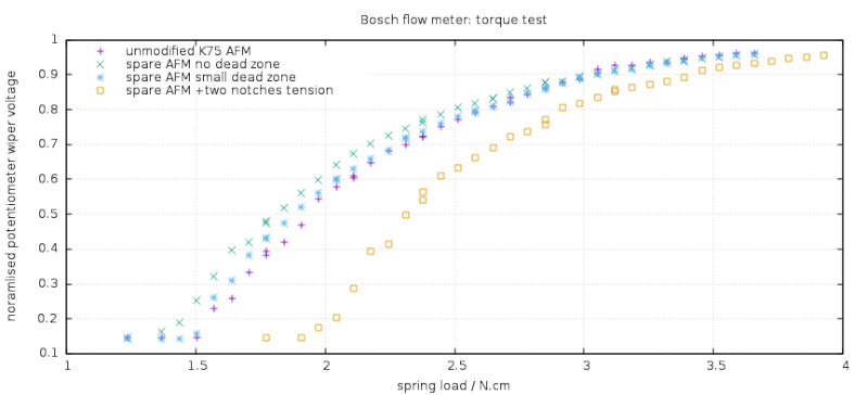
As can be seen, it is quite close to the AFM that was on the K75 to start with opening just a tad earlier then having higher output through low and mid range; then almost identical at top of the range. The optimal mixture screw setting now comes out somewhere in the mid portion of its adjustment range. ( instead of bottoming out as before ).

I'm very pleased with last road test. The bike's a real pleasure, running better and has more power than before. Especially the low throttle pick is a lot smother. This is the unit I've adjusted to get a clean new track on the carbon and is now better than the original unit which  left I unmodified. Thanks to Charlie for that suggestion.

It will be interesting to see how this looks on the gas analyser, but I won't be too inclined to move it now anyway.

My conclusion thus far is that if there is some movement in the AFM unit over time that merit a little fine tuning it is probably best done by tweaking the amount of dead zone on the wiper.  If it is necessary to change the position of the wiper because of bad track wear on the potentiometer, this will need resetting anyway.

I'll wait to see the results of the gas analysis and then summarise all this in a new thread.


67Back to top Go down   Flowmeter restoration - Page 2 Empty Re: Flowmeter restoration Tue Apr 12, 2016 11:20 am

Beamer

Beamer
Platinum member
Platinum member
Had a quick run of the restored unit and the unmodifies K75 AFM ( 2nd and 3rd lines on the above graph ) on a gas analyser this arvo.

Air fuel ratio at tick over was 14.70 for former and 14.45 for latter. Did not have a rolling road to do realistic mid and high range checks.

The refurbished unit is a little stronger in mid-range , the original a little better between 6 and 8000 rpm.


This is probably reflects what is shown in the graph, with the spare unit seeming to have a slightly more rounded curve and having been set up to open slightly earlier, giving a little more fuel in low to mid range.

Anyway, from starting with a 2nd hand unit with a badly worm track, I now have well setup unit with a clean, new wiper track. Should be good for another 10 years at least.

The improvement in the bikes performance, for a little TLC, has well paid off the effort. I'm still surprised how well it takes off every time I open the throttle. Wink

The new power is pointing out the next job is an overhaul of the suspension which is not stable enough for my liking throwing it into bends. I actually much preferred the K100 for road handling ( and braking !! ) .


68Back to top Go down   Flowmeter restoration - Page 2 Empty Re: Flowmeter restoration Tue Apr 12, 2016 4:19 pm

Beamer

Beamer
Platinum member
Platinum member
Just throwing in this close up of a worn track. This track wear is pretty typical of these units now, not a bad example.

Flowmeter restoration - Page 2 Boscha15


Though less clear in the photo,  the dark lines on either side of wear mark tracks are a collection carbon power. This is easily blown off.

Note the usually sharp laser cuts in the green resistor blocks have gone fuzzy. This unit was badly stored. This is unusual degradation since on a bike they are well protected and usually look nearly new.


69Back to top Go down   Flowmeter restoration - Page 2 Empty Re: Flowmeter restoration Tue Apr 12, 2016 7:40 pm

robmack

robmack
Life time member
Life time member
Been following this thread with interest.  A quick question Beamer:  Did you get your additional MAF units from wrecked autos in the junk yard?  Or are they k-bike Ebay purchases?


__________________________________________________
Robert
1987 K75 @k75retro.blogspot.ca
http://k75retro.blogspot.ca/
    

70Back to top Go down   Flowmeter restoration - Page 2 Empty Re: Flowmeter restoration Tue Apr 12, 2016 7:56 pm

Beamer

Beamer
Platinum member
Platinum member
Not ebay but they are second hand K-bike units.

It may be possible to use car units if you swap the return spring. These are different for different vehicles and are identified by the number which is repeated around the adjustment ring. : 012 for the bikes. I have not investigated in detail but I think the resistor networks will be the same. Just take care to find out whether it is a linear or logarithmic resistor chain.

Later models did not use the funky log output and dealt with the conversion in software.  These will be identical on the outside ( apart from serial number ) but should be detectable by checking resistances pins 5,8 ; pins 5.9 but I cannot advice on actual values.

To be honest there seem to be enough 2nd hand K ones lying around at about $20-25. I would not waste time unless stuck.

I'm in the process of writing all this up into a clear guide. But it'll take a bit of time to do it properly.


This effort has now been summarised in a more concise account as a separte thread. Thanks for those who helped in discussing this here.

https://www.k100-forum.com/t11055-bosch-air-flow-meter-restoration-summary#131826


Sponsored content


View previous topic View next topic Back to top  Message [Page 2 of 2]

Go to page : Previous  1, 2

Permissions in this forum:
You cannot reply to topics in this forum