BMW K bikes (Bricks)


You are not connected. Please login or register

Go to page : 1, 2  Next

View previous topic View next topic Go down  Message [Page 1 of 2]


1Back to top Go down   Wiring an Acewell Speedometer Empty Wiring an Acewell Speedometer Fri Nov 11, 2011 3:25 pm

kringb

kringb
Silver member
Silver member
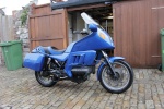
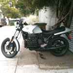
I am installing an Acewell Speedometer (2853) on my 85 K100

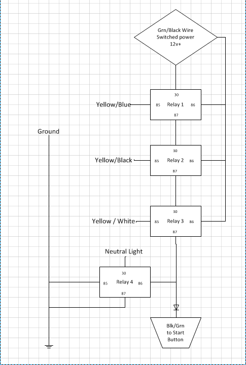
The thread by rbarrero ( http://k100rt.aforumfree.com/t2611-my-k100-cafe-racer-project-story ) helped make the basic installation very easy. I plan to follow the instructions outlined in that thread on enabling the bike to start in neutral.

The speedometer has two functions which I am currently not using but would like to. Fuel Gauge and Hazard Light.

Fuel Gauge
My bike has the 7L/4L warning lights and I don't believe that the fuel sensor can be adapted to a gauge.

I am wondering if I could instead use the fuel guage as a temperature guage. My bike came with only a temperature warning light. I am using a water pump from a newer bike and the coolant drain plug is a temperature sensor. Is it possible, or what would be required, to hook this up to the fuel gauge to use it as a temperature guage.

Or, is it possible to use the fuel gauge in some crude way with my existing low fuel level warning wiring?

Hazard Light

Depending on what I use the fuel gauge for, I assume that one option for this would be to use it as my water temp warning light. Would another option be to use it as a fuel level warning light?

From what I have read on other forums, I don't think that this could be used for the battery warning light without modifying the speedometer wiring. Is this true, or is this another option for the light?

----

Thanks for any advice on this. I don't have much experience with electrical wiring but am learning what I need to as I go along.


2Back to top Go down   Wiring an Acewell Speedometer Empty Re: Wiring an Acewell Speedometer Fri Nov 11, 2011 10:49 pm

Inge K.

Inge K.
VIP
VIP
kringb wrote:I am wondering if I could instead use the fuel guage as a temperature guage. My bike came with only a temperature warning light. I am using a water pump from a newer bike and the coolant drain plug is a temperature sensor. Is it possible, or what would be required, to hook this up to the fuel gauge to use it as a temperature guage.
Could be done, as both working with resistance to ground. But first you have to find out the resistance
working area for the Acewell instrument, and then find a sensor that match.
(resistance is normally a lot lower for a level sensor, than a temp. sensor).
Another side is that it seems like the Acewell only got four segments for this, so it ain`t gonna be that
much useful is my opinion.

Inge K.


3Back to top Go down   Wiring an Acewell Speedometer Empty Re: Wiring an Acewell Speedometer Sat Nov 12, 2011 2:13 am

kringb

kringb
Silver member
Silver member
On the Acewell wiring diagram there is a zig zag line and next to that it says 100 ohms. Is that the resistance working area? I should be able to find out the resistance area on the temperature sensor but you might be right about it not being useful.

I looked into my temp warning light and tried hooking it up to the hazard light on the speedometer but it won't work. The temp relay sends a -12V but the hazard bulb needs +12V. I believe that is the case with the battery sensor too.

I would still like to use the fuel gauge and hazard for something. I will try to look into my fuel level sensor next and try to understand what power it output.


__________________________________________________
85 k100rs | 78 xs650
    

4Back to top Go down   Wiring an Acewell Speedometer Empty Re: Wiring an Acewell Speedometer Sat Nov 12, 2011 12:40 pm

Inge K.

Inge K.
VIP
VIP
Temp. sensor: ~4K ohm cold, ~200 ohm at 95 celsius. (this values is for the additional sensor on a K1100, I`ll guess they all is similar).


About hazard w. light: why not use it for what is ment for, add a hazzard light switch.

If you want to use it for temp. warning, just add a relay.
Since you have the plan to do as rbarrero, using relays on neutral interlock bypass, add one more relay.
Look at my first suggestion for the hazzard warning, use the same wiring...but use the signal from the
temp. relay to ground the coil.

Inge K.


5Back to top Go down   Wiring an Acewell Speedometer Empty Re: Wiring an Acewell Speedometer Mon Nov 21, 2011 1:20 pm

kringb

kringb
Silver member
Silver member
As I said, wiring is a weak spot of mine but I have studied your suggestions, Inge, and I think I understand how to follow them to build the neutral interlock bypass and to connect my temp sensor to the hazard light.

I still have a question on the fuel gauge. The speedometer gauge works off a resistance 0 to 100 ohms of -12V. With a connection to directly to ground the gauge reads full.

I don't fully understand how my sensors are working. I have the thermistors that trigger the 7L and 4L lights. With the aid of two "NPN transistors" it seems to send +12V to either light.

this link explains the system. I have read it many times and still have only a weak grasp of it. http://hrsbstaff.ednet.ns.ca/bvogel/K100/download/electrical/fuel%20sensors/fuel%20level%20sensors.htm

I would like to use the Acewell guage as an indicator of when I reach either the 7L or 4L level. Either would be fine. So the gauge would jump to full when hit one of those low fuel levels. I assume that I would need another relay just like the temp/Hazard setup.

The problem, I believe is that the "NPN transistors" are buried in the stock instrument cluster.

Does anyone know if that is true or if there is any way to accomplish what I am trying to do?

I really appreciate any help I can get.


6Back to top Go down   Wiring an Acewell Speedometer Empty Re: Wiring an Acewell Speedometer Mon Nov 21, 2011 3:51 pm

charlie99

charlie99
VIP
VIP
i think you will find that more than just the npn transistors are housed in the instrument cluster , i would be thinking all the other suport electronics is there as well .

the basic circuit turns the lamps on when activated ....what happens is that the 12 volts is already fed through the lamps and the transistors switch on ....grounding the low side of the globe .

you would need to duplicate the opamp parts of the circuit to maintain the current configuration if you toss the instruments (not hard to do ) but a rethink on the output operations would be needed to operate the acewell properly as its looking for a resistance path rather than a voltage switch path ...but not impossible at all ...why not substitute a relay which in turn would switch into circuit a resistor of an appropriate value


__________________________________________________
cheezy grin whilst riding, kinda bloke ....oh the joy !!!! ...... ( brick aviator )

'86 K100 RT..#0090401 ..."Gerty" ( Gertrude Von Clickandshift ) --------O%O
'86 k100 rs.. #######..  "Fred " (f(rame) red ) ( Fredrick leichtundschnell ) - -
bits and pieces from many kind friends across the k100 world ...with many thanks ..
1987 k100rs ########   "Red"  - (red sports rs TWB style )
1989 K100rt #009637   "Black Betty"  (naked rt ala Nigel , now sporting an rs main fairing )
    

7Back to top Go down   Wiring an Acewell Speedometer Empty Re: Wiring an Acewell Speedometer Mon Nov 21, 2011 5:12 pm

kringb

kringb
Silver member
Silver member
why not substitute a relay which in turn would switch into circuit a resistor of an appropriate value

Thanks for the response and the suggestion. Could you please tell me if this understanding close to correct?
------
I have two wires (one from each thermistor).
When the fuel is above the thermistors I have +12V with a resistance of 600 ohms. on each wire.
If the fuel drops below the level on either resistor I will get +12V with a resistance of 53 ohms from the respective wire.

The Acewell fuel gauge measures empty when -12V with a resistance of 100 ohms or higher is applied.
The Acewell fuel gauge measures full when -12V with a resistance of 0 ohms is applied.
The two gauge segments in between full and empty probably get triggered at apx 35 ohms and 70 ohms.

In order to use one of my thermistors to trigger the fuel gauge I would need to install a relay that would switch on when it recieves +12V with 53ohms from the thermistor. The relay would connect a circuit of -12V. This would have 0 ohms resistance so this could be used to directly connect to the gauge, giving a reading of Full.

---

If this basic understanding is correct then I can ask about adding in resistors to a circuit to more fully use the fuel gauge.


8Back to top Go down   Wiring an Acewell Speedometer Empty Re: Wiring an Acewell Speedometer Mon Nov 21, 2011 6:01 pm

charlie99

charlie99
VIP
VIP
just replace the globes with the relays is what i meant

you will still need the comparitor part of the circuit (op amps ) and the constant current source and voltage reference , the thermistors in themselves dont change their resistance reliably unless they have a certain amount of current already flowing through them = heating effect which makes them 600 od ohms when cooled by the fuel around them and 35 ohms when there is no cooling effect (ie they get hot ) without the heating effect they would not change values verry well as the ambient temperature would be close to the same as the fuel

i think they are ntc (negative temperature co-efficient ) type thermistors so they get less resistance when hot i could be wrong on the operation if they were ptc thermistors in which case the operational values are reversed

if this all sounds way too hard ...might just be easier to buy a later model tank with the float type guage sender . do the wiring conversion for the fuel pump and the mounting bracket conversion and your away


hope this helps


9Back to top Go down   Wiring an Acewell Speedometer Empty Re: Wiring an Acewell Speedometer Mon Nov 21, 2011 6:26 pm

kringb

kringb
Silver member
Silver member
The op amps and voltage reference are the pieces of the puzzle that are throwing me. I will take some time and do a little more research to see if I can understand.

I hate to admit defeat and I also hate to waste anything. So, seeing that fuel gauge sitting there unused will pester me until I work something out. But, I am not going to hold off any longer on the other changes .

Thanks again for your help


__________________________________________________
85 k100rs | 78 xs650
    

10Back to top Go down   Wiring an Acewell Speedometer Empty Re: Wiring an Acewell Speedometer Mon Nov 21, 2011 6:32 pm

charlie99

charlie99
VIP
VIP
it shouldnt be too hard to replicate the circuit in the instruments and make it into a small box ...housed maybe under the tank or in the electrics box ...

or even to rip out the circuit board and put it in a box to protect it ..with a couple of relays to add the right resistance values

good luck


11Back to top Go down   Wiring an Acewell Speedometer Empty back add it and in need of help Thu Mar 22, 2012 12:08 pm

kringb

kringb
Silver member
Silver member
I started this thread back in November but a move and some other personal things kept me from wiring up the speedometer. Now I am back at it and in need of help.

I'm just trying to get the neutral light, hazard light, and Gear Position Indicator working (not the fuel gauge) but I am having trouble getting the relays to correctly light my neutral and hazard (temp warning) lights.

As I said in the first post, I have reproduced the set up as shown by rbarrero at the link above. I am also following Inge's wiring diagram here or Comment # 30 on rbarrero's thread linked above.

I think I have the wiring done correctly but am having trouble with the behavior of the relays. I copied rbarrero so much that I actually blew up his photo of the relays that he used and was able to identify them. So I am using Omron G3MC-202P-DC12 solid state relays. Here is the info on this relay.

On this relay there are four pins labeled +4, -3, 2, and 1. On the load side I have the +12V at #4, the ground on #3. On the output side I have +12V at #1 and #3 goes to the light (or next relay in the case of the Gear Position Indicators) I will ignore the neutral relay for now.

When I close the circuit on pins #4 and #3 then I correctly get +12v on pin #2 and by using a simple test light it will light. But, and finally here is my problem, when I open the circuit on the load pins the test light on pin #2 stays on. If I remove the test light (or if there is no test light applied to pin #2 then the circuit between #1 and #2 correctly opens. Because of this, the Gear Position Indicator relays are working but the Hazard light will not. Once lit it stays lit. Also the neutral light is not working but I am not sure if that is because of the same problem or because I can not make a ground connection between pins 1 and 2 with this relay.

Am I using the wrong relays or am I missing some other pieces to this?


12Back to top Go down   Wiring an Acewell Speedometer Empty Re: Wiring an Acewell Speedometer Thu Mar 22, 2012 1:19 pm

Inge K.

Inge K.
VIP
VIP
kringb wrote:On this relay there are four pins labeled +4, -3, 2, and 1. On the load side I have the +12V at #4, the ground on #3. On the output side I have +12V at #1 and #3 goes to the light (or next relay in the case of the Gear Position Indicators)

Data sheet shows: 1 & 2 load, 3+, 4-.

This would give following connection:
#1 12v+, #2 next relay, #3 12V+, #4 GPI switch.


__________________________________________________
Inge K.
K100RS -86. (first owner), K1100LTSE -94.
    

13Back to top Go down   Wiring an Acewell Speedometer Empty Re: Wiring an Acewell Speedometer Thu Mar 22, 2012 1:59 pm

kringb

kringb
Silver member
Silver member
Sorry, I mistyped. That is how I have it connected. +12V to #3, GPI to # 4.

For the GPI function it is working . It is when i hook a light up to the output that I have the problem of the light not going out even when the load it totally removed.

------

While looking around for an answer I came across a comment about solid state relays that they "have a minimum current draw. When a solid state relay does not have enough current passing through it, it will turn on but will not turn back off" link to source .

The datasheet for the relay that I am using says that the output load current is .1 to 2A. Does this mean the minimum is .1 A? Surely I have more than that going through.


14Back to top Go down   Wiring an Acewell Speedometer Empty Re: Wiring an Acewell Speedometer Thu Mar 22, 2012 2:48 pm

Inge K.

Inge K.
VIP
VIP
kringb wrote:Surely I have more than that going through.
Isn`t the warning lights in the Acewell LEDS? = minimal current draw.


__________________________________________________
Inge K.
K100RS -86. (first owner), K1100LTSE -94.
    

15Back to top Go down   Wiring an Acewell Speedometer Empty Re: Wiring an Acewell Speedometer Thu Mar 22, 2012 3:08 pm

kringb

kringb
Silver member
Silver member
yes they are LEDs. Maybe my test light is also.

I am learning about electricity as I go along and have a pretty limited understanding. So the LED or the draw of power might be less than 1 amp. I don't understand why the relay works properly when there is no draw attached?

What would be the best way to increase the current draw? I guess I would only need that for the two relays that I am using for the lights (hazard and neutral)

Is there any problem with using this relay (and any increased draw solution) to make the switch from +12V to ground for the neutral light?

(By the way, thank you Inge. Your posts and your initial diagram have been a really great help)


16Back to top Go down   Wiring an Acewell Speedometer Empty Re: Wiring an Acewell Speedometer Thu Mar 22, 2012 5:44 pm

Inge K.

Inge K.
VIP
VIP
Thanks for the encouraging words, can`t take credit for the initial diagram, as this is an idea from Drake Smith aka Flying Duck from Seattle.

About the solid state relay function...have never used any...then no need to study the function.

I think the easiest solution would be to change out the two last relays with ordinary ones, but others on this forum might have other ideas.

Not quite sure what you mean in the last sentence, but it`s many years since I was a schoolboy....and this isn`t my native language.


__________________________________________________
Inge K.
K100RS -86. (first owner), K1100LTSE -94.
    

17Back to top Go down   Wiring an Acewell Speedometer Empty Re: Wiring an Acewell Speedometer Sat Mar 24, 2012 2:03 am

kringb

kringb
Silver member
Silver member
Thanks, I may end up going with mechanical relays if I can't find a solution soon. To add to the mystery I discovered today that the relays do not work at all when connected to the led in the speedometer. If I have a closed circuit on the load, the output circuit will not close if connected to the led. if the output is connected to just my test light then the circuit will close correctly but will not reopen until the test light is removed. If no draw is connected to the output then the relay works correctly (opening and closing the load circuit opens and closes the output).


18Back to top Go down   Wiring an Acewell Speedometer Empty Re: Wiring an Acewell Speedometer Sat Mar 24, 2012 3:10 am

charlie99

charlie99
VIP
VIP
leds draw under .03 amps usually ...more like .02 amps as a general rule, a globe would draw about 1/3 -1/2 ( .3 -.5 )an amp

of corse you could always get higher powered globe maybe or a load resistor say 10 watt x 22 ohms ...this will get kinda warm though, so best to put it in a well aired area

but more than likely you might need to load each relay on its output with a small load lets say a 100 ohm 5 watt type resistor ...(.15 amps )

rbarrow? (sp ) did an acewell conversion a while ago using solid state relays i think might be an idea to look for the thread ...the wiring diagram was also in that thread as well ...with lots of help from inge

http://k100rt.aforumfree.com/t2611-my-k100-cafe-racer-project-story


Last edited by charlie99 on Sat Mar 24, 2012 3:22 am; edited 2 times in total


__________________________________________________
cheezy grin whilst riding, kinda bloke ....oh the joy !!!! ...... ( brick aviator )

'86 K100 RT..#0090401 ..."Gerty" ( Gertrude Von Clickandshift ) --------O%O
'86 k100 rs.. #######..  "Fred " (f(rame) red ) ( Fredrick leichtundschnell ) - -
bits and pieces from many kind friends across the k100 world ...with many thanks ..
1987 k100rs ########   "Red"  - (red sports rs TWB style )
1989 K100rt #009637   "Black Betty"  (naked rt ala Nigel , now sporting an rs main fairing )
    

19Back to top Go down   Wiring an Acewell Speedometer Empty Re: Wiring an Acewell Speedometer Sat Mar 24, 2012 3:10 am

Rick G

Rick G
admin
admin
I would be going with mechanical relays. LEDs and solid state relays don't mix well I have seen many problems. You could put a 180 ohm resistor across the LED which will give a bit more current draw.
With solid state you may need to make A switch B and B switch C relay where with a mechanical each wire can switch a relay and the contacts put in series to light the LED.


__________________________________________________
"Man sacrifices his health in order to make money.
Then he sacrifices money to recuperate his health.
And then he is so anxious about the future that he does not enjoy the present; the result being that he does not live in the present or the future; he lives as if he is never going to die, and then dies having never really lived."   Dalai Lama


Bikes 1999 K1100 LT with a Big Block 1200
    

20Back to top Go down   Wiring an Acewell Speedometer Empty Re: Wiring an Acewell Speedometer Wed Mar 28, 2012 3:23 am

kringb

kringb
Silver member
Silver member
Well, I tried adding resistors and no luck. I was able to get some more clues but I am not sure wher to take them to find the solution. If anyone can help shed any light on this I would really appreciate it. The mechanical relays are a fallback option but, because I would need five of them, I would rather solve this with the solid state relays that I have. As you will see from my clues it does not seem to be a problem with the led themselves. Here is what I found:

This is all with a relay that has +12v supply on one side of the relay load and I am trying to get 12v output the other side.

Without anything hooked up to the output the relay works great. By closing the input circuit I get +12v coming out. When I open the input circuit the output correctly drops back to 0.

With the led connected to the output: when I close the input circuit I get +2.35v on the output (and the light does not go on). When I open the input circuit the output remains at +2.35v.

With two resistors connected parallel to the led I get a bit more (about +2.5v) but otherwise the same as above.

With just the two resistors connected I get +.2v on the output. Again, the output circuit stays closed after opening the input. The resistors are 120 ohm each. The man at the electrical shop calculated that I would need one resistor to draw .1 A which is the relays minim load. (he did not know anything about my relays. I bought those online).

Lastly, when I connect the speedometers main power wire to the relay output the relay works correctly. It only outputs 2.2 v but the speedometer backlight comes on and it goes off when the input circuit is opened. The oil led light does not come on however.

So that's it. I am not sure where to turn with this now. could it have something to do with the fact that the relay's rated output is 2A at 100 to 240 VAC? I looked for relays that output +12v but they look ver large and heavy duty.


When I


21Back to top Go down   Wiring an Acewell Speedometer Empty Re: Wiring an Acewell Speedometer Wed Mar 28, 2012 6:29 am

charlie99

charlie99
VIP
VIP
better post up a pic of the relays ....then we can look them up ... but your along the right path ..

dont forget leds are about 2 volts drop across them.. green i think about 2.3 v ...the output of the solid state relays is kinda like a transistor so about .6 volts might be about right ...but im thinking these particular relays have back emf protection on them as well (internaly... diodes across the junction )

the only other thing i can think of is that the input is connected to the output side ?

last hope is you can get minature relays ....good for about 2 amps ...and only about a square centimeter in size


__________________________________________________
cheezy grin whilst riding, kinda bloke ....oh the joy !!!! ...... ( brick aviator )

'86 K100 RT..#0090401 ..."Gerty" ( Gertrude Von Clickandshift ) --------O%O
'86 k100 rs.. #######..  "Fred " (f(rame) red ) ( Fredrick leichtundschnell ) - -
bits and pieces from many kind friends across the k100 world ...with many thanks ..
1987 k100rs ########   "Red"  - (red sports rs TWB style )
1989 K100rt #009637   "Black Betty"  (naked rt ala Nigel , now sporting an rs main fairing )
    

22Back to top Go down   Wiring an Acewell Speedometer Empty Re: Wiring an Acewell Speedometer Wed Mar 28, 2012 8:10 am

robmack

robmack
Life time member
Life time member
If you decide to go the conventional relay route and are concerned about the physical size of the relay, then consider getting encapsulated micro relays from Eastern Beaver. These relays are extremely small in size yet handle 20A of load current. At about $7 each they are a tad pricey but the size benefit offsets that cost.


__________________________________________________
Robert
1987 K75 @k75retro.blogspot.ca
http://k75retro.blogspot.ca/
    

23Back to top Go down   Wiring an Acewell Speedometer Empty Re: Wiring an Acewell Speedometer Wed Mar 28, 2012 8:40 am

Rick G

Rick G
admin
admin
Check out Radio Shack I got some very small 12v relays that were meant to be mountes on a printed circuit board, the three together were about the same size as a pencil sharpner.


__________________________________________________
"Man sacrifices his health in order to make money.
Then he sacrifices money to recuperate his health.
And then he is so anxious about the future that he does not enjoy the present; the result being that he does not live in the present or the future; he lives as if he is never going to die, and then dies having never really lived."   Dalai Lama


Bikes 1999 K1100 LT with a Big Block 1200
    

24Back to top Go down   Wiring an Acewell Speedometer Empty Re: Wiring an Acewell Speedometer Wed Mar 28, 2012 10:45 am

kringb

kringb
Silver member
Silver member
Thanks fir the responses. I posted before going to sleep and woke up to these new options and things to consider. I am very close to giving up on the solid state relays but not quite yet. But it is very good to know that the mechanical route may have better options than I thought.

Charlie, I posted a link to the data sheet on my relays in post #11 above. If you could take a look and let me know if you see anything in there I would appreciate it. I think it is a PDF file. If you can't view that let me know and I can try to get it up in some other format. Please also note, in that post I mistyped on the hook up of my positive and negative. I corrected it a few posts down.


25Back to top Go down   Wiring an Acewell Speedometer Empty Re: Wiring an Acewell Speedometer Wed Mar 28, 2012 12:08 pm

charlie99

charlie99
VIP
VIP
i think we have a winner answer to the problem ....these relays are designed for ac load operation

they are designed with an internal snubber circuit and opto triac operation with zero crossover switching

meaning that they will not turn off properly in a dc type circuit as there is no progression from positive to negative going waveforms or visa versa

yes you may be able to trick them into working under certain conditions ...but better to choose a different device

http://www.omron247.com/doc/pdfcatal.nsf/2F2510BA6617412D8625776800023318/$FILE/090600_OMRON_G3MCcatasheet_J28I-E-01.pdf

its a pitty really that we couldnt use a 4073 cmoc ic .....this is a triple input "and" gate ....meaning it would not turn on till all inputs have become high at the same time ...then use the ssr to switch the lamp on for neutral etc ... 2 small parts to do the whole neutral sensing thang ....just some thoughts (but probably got my logic wrong again )


__________________________________________________
cheezy grin whilst riding, kinda bloke ....oh the joy !!!! ...... ( brick aviator )

'86 K100 RT..#0090401 ..."Gerty" ( Gertrude Von Clickandshift ) --------O%O
'86 k100 rs.. #######..  "Fred " (f(rame) red ) ( Fredrick leichtundschnell ) - -
bits and pieces from many kind friends across the k100 world ...with many thanks ..
1987 k100rs ########   "Red"  - (red sports rs TWB style )
1989 K100rt #009637   "Black Betty"  (naked rt ala Nigel , now sporting an rs main fairing )
    

26Back to top Go down   Wiring an Acewell Speedometer Empty Re: Wiring an Acewell Speedometer Wed Mar 28, 2012 5:40 pm

kringb

kringb
Silver member
Silver member
Thanks Charlie. It is good to know the reason. I guess I should have spent more time researching the relays and less time in photoshop trying to copy someone else. Anyway, onward and upward.

I tried to look up a solid state relay that switches DC to DC but they are all pretty expensive, apx. over $14 each. Also, after reading about problems with SSR and leds I am now nervous to try again. Unless someone can suggest a cheap basic ssr that should work, I will try the mechanical route.


Last edited by kringb on Wed Apr 11, 2012 12:14 pm; edited 1 time in total


27Back to top Go down   Wiring an Acewell Speedometer Empty Re: Wiring an Acewell Speedometer Fri Mar 30, 2012 1:36 am

kringb

kringb
Silver member
Silver member
I checked out the 4073 CMOS and your suggestion, Charlie, seems like a good one to me. If I were braver or more knowledgeable I would try it. After all this I now think the cleanest solution to the whole thing might be to use the 4073 CMOS for the neutral lock and then open up the speedometer and change the wiring for the netral light (and hazard light if wanted). In another forum post, about installing an Acewell on an airhead, a person who used to work for Acewell wrote in and said this would not be difficult. I am afraid to open the speedometer though. I don't want to compromise it's weather proof seal.

At radio shack I found a very small mini relay that is 12V 1 amp. I tried one on the hazard light and it worked. Does anyone know if this would be large enough to handle the gear position neutral interlock also?

This 1 amp mini relay has 5 pins. From my understanding, this fifth pin, 87a, could be ignored. I am going to actually snip it off, or bend it up so that it does not stick through the circuit board because it gets in the way of my planned solder paths. I don't suppose ther is any harm in doing that?


28Back to top Go down   Wiring an Acewell Speedometer Empty Re: Wiring an Acewell Speedometer Fri Mar 30, 2012 1:44 am

Rick G

Rick G
admin
admin
The 1 amp relay would be more than adequate for the job and removing the 87a pin is ok as it is only a second pin in common with 87.


__________________________________________________
"Man sacrifices his health in order to make money.
Then he sacrifices money to recuperate his health.
And then he is so anxious about the future that he does not enjoy the present; the result being that he does not live in the present or the future; he lives as if he is never going to die, and then dies having never really lived."   Dalai Lama


Bikes 1999 K1100 LT with a Big Block 1200
    

29Back to top Go down   Wiring an Acewell Speedometer Empty Re: Wiring an Acewell Speedometer Fri Mar 30, 2012 3:03 am

charlie99

charlie99
VIP
VIP
thats fine mate ....its just a common pin on the armature of the relay common ....yes it will do the job fine .


__________________________________________________
cheezy grin whilst riding, kinda bloke ....oh the joy !!!! ...... ( brick aviator )

'86 K100 RT..#0090401 ..."Gerty" ( Gertrude Von Clickandshift ) --------O%O
'86 k100 rs.. #######..  "Fred " (f(rame) red ) ( Fredrick leichtundschnell ) - -
bits and pieces from many kind friends across the k100 world ...with many thanks ..
1987 k100rs ########   "Red"  - (red sports rs TWB style )
1989 K100rt #009637   "Black Betty"  (naked rt ala Nigel , now sporting an rs main fairing )
    

30Back to top Go down   Wiring an Acewell Speedometer Empty Re: Wiring an Acewell Speedometer Sat Mar 31, 2012 2:55 am

kringb

kringb
Silver member
Silver member
Don't leave me just yet. I haven't quite ridden off into the sunset. I soldered up the relays and gave it a try. They lit the lights correctly and sent 12v through to the start button when in neutral. They click very loud when they make the switches. About as loud as a pencil being snapped in two. Is that normal?

The bigger problems are that the neutral light comes on whenever the clutch is pulled in (in addition to when it is in neutral). I guess the clutch overide of the neutral interlock is sending power to tha start button wire. I think this problem was overlooked in the wiring diagram that I am using. Or did I miswire something.

The other problem is that the bike won't start in neutral. It has 12v going to the start button but when you press it the starter makes a funny weak sound. It is not a low battery sound it is like a spinning rattle that sounds like it is not getting enough juice. If I pull in the clutch it starts just fine. I tried to check the amps in the start button wires but in doing so I blew my last fuse.

Any ideas?


31Back to top Go down   Wiring an Acewell Speedometer Empty Re: Wiring an Acewell Speedometer Sat Mar 31, 2012 3:26 am

charlie99

charlie99
VIP
VIP
hmm i better look in the circuits again

pity inge hasnt piped in ...he must be away or at least lost his internet i guess

for some of those relays yes they do click rather loudly (i recon there actually under wound for 12 volts more like 9 or so ) maybe you can get some thong (jandle , flip flop whatever you call it there ) rubber and pack the relays to provide some sort of absorbtion of the sound ? as this would be pronounced if mounted to any of the frame members i guess .

im thinking that the clutch overide and neutral may have some form of feedback from the old circuitry and may need a diode or two to stop that happening


__________________________________________________
cheezy grin whilst riding, kinda bloke ....oh the joy !!!! ...... ( brick aviator )

'86 K100 RT..#0090401 ..."Gerty" ( Gertrude Von Clickandshift ) --------O%O
'86 k100 rs.. #######..  "Fred " (f(rame) red ) ( Fredrick leichtundschnell ) - -
bits and pieces from many kind friends across the k100 world ...with many thanks ..
1987 k100rs ########   "Red"  - (red sports rs TWB style )
1989 K100rt #009637   "Black Betty"  (naked rt ala Nigel , now sporting an rs main fairing )
    

32Back to top Go down   Wiring an Acewell Speedometer Empty Re: Wiring an Acewell Speedometer Sat Mar 31, 2012 3:31 am

Rick G

Rick G
admin
admin
There is a diode in the original instrument cluster to take care of that. You will need a fair size diode, 1 amp or so and put it in the wire that goes from the last relay to the LED with the stripe on it towards the LED and it should work OK


__________________________________________________
"Man sacrifices his health in order to make money.
Then he sacrifices money to recuperate his health.
And then he is so anxious about the future that he does not enjoy the present; the result being that he does not live in the present or the future; he lives as if he is never going to die, and then dies having never really lived."   Dalai Lama


Bikes 1999 K1100 LT with a Big Block 1200
    

33Back to top Go down   Wiring an Acewell Speedometer Empty Re: Wiring an Acewell Speedometer Sat Mar 31, 2012 3:42 am

charlie99

charlie99
VIP
VIP
just look for an 1n4002 , 1n4004 or 1n4007 all 1 amp types just different voltages ....could cost you 10 cents for a couple maybe

but from radio shack could be a couple of dollars ....giggle


__________________________________________________
cheezy grin whilst riding, kinda bloke ....oh the joy !!!! ...... ( brick aviator )

'86 K100 RT..#0090401 ..."Gerty" ( Gertrude Von Clickandshift ) --------O%O
'86 k100 rs.. #######..  "Fred " (f(rame) red ) ( Fredrick leichtundschnell ) - -
bits and pieces from many kind friends across the k100 world ...with many thanks ..
1987 k100rs ########   "Red"  - (red sports rs TWB style )
1989 K100rt #009637   "Black Betty"  (naked rt ala Nigel , now sporting an rs main fairing )
    

34Back to top Go down   Wiring an Acewell Speedometer Empty Re: Wiring an Acewell Speedometer Sat Mar 31, 2012 4:14 am

kringb

kringb
Silver member
Silver member
I had to look up what a diode was but I think I now understand. On my circuit board set up I have the three gear position indicators which send +12v down a line directly to the relay that switches it to -12v for the neutral led. Branching off this line from the three gear position relays is the connection that leads to the wire to the start button. I would need to Insert the diode anywhere after that branch in the line to the start button, correct?

I can see how this would prevent the clutch from lighting the neutral light but how about the starting problem? I thought that might be due to too low amps coming through my relay contraption but can that be ruled out if I have 12v coming out?


35Back to top Go down   Wiring an Acewell Speedometer Empty Re: Wiring an Acewell Speedometer Sat Mar 31, 2012 5:08 am

charlie99

charlie99
VIP
VIP
sounds about right to me ,,,

the non start just could be an intermittent engaging sprag clutch ...maybe ?

when you get her going ...run some diesel oil in the beast for a few thousand ...this is suposed to clean up all the gunge and crap that accumulates as residue in the upper parts of the motor as well as grabbing all the carbon deposits around the main engine just by the nature of the oil and its components too scavange dirt from inside ..


__________________________________________________
cheezy grin whilst riding, kinda bloke ....oh the joy !!!! ...... ( brick aviator )

'86 K100 RT..#0090401 ..."Gerty" ( Gertrude Von Clickandshift ) --------O%O
'86 k100 rs.. #######..  "Fred " (f(rame) red ) ( Fredrick leichtundschnell ) - -
bits and pieces from many kind friends across the k100 world ...with many thanks ..
1987 k100rs ########   "Red"  - (red sports rs TWB style )
1989 K100rt #009637   "Black Betty"  (naked rt ala Nigel , now sporting an rs main fairing )
    

36Back to top Go down   Wiring an Acewell Speedometer Empty Re: Wiring an Acewell Speedometer Sat Mar 31, 2012 7:16 pm

Inge K.

Inge K.
VIP
VIP
kringb wrote:Branching off this line from the three gear position relays is the connection that leads to the wire to the start button. I would need to Insert the diode anywhere after that branch in the line to the start button, correct?

I thought that might be due to too low amps coming through my relay contraption but can that be ruled out if I have 12v coming out?
A diode shouldn`t be needed in this setup, as the neutral light now is isolated from the starter interlock circuit.
Or have you connected the black/green wire at the multiconnector to something in the Acewell wiring?

And I think you`re right about the to low amp through the three relay setup theory, a bad solder point somewhere?

Inge K.


__________________________________________________
Inge K.
K100RS -86. (first owner), K1100LTSE -94.
    

37Back to top Go down   Wiring an Acewell Speedometer Empty Re: Wiring an Acewell Speedometer Sun Apr 01, 2012 3:18 am

kringb

kringb
Silver member
Silver member
I knew it wasn't the sprag clutch because I had recently been in there and it is clean. So I took a close look at my sodering and was able to track it down to my wiring. I was using the green/black switched 12v to power pin #30 on my first relay. For some reason I chose to use the blue/grey wire to send +12v to the #86 pin on the three gear position relays. On this wire I am only getting 11.85v. Using the green/black wire to power the relays solved the starting problem.

The neutral light still lights when the clutch is engaged and I am not sure why. The black/green wire runs from pin #87 of relay#3 with a branch off to pin #86 of the neutral light relay. I don't have anything else hooked up to that wire. I am having a hard time reading the wiring diagram in my Clymer manual because it seems to have the wire colors wrong. But I am suspecting that somewhere between my relay board and the start button, the clutch start permission wire is branching in. It is sending +12v to the start button and that power is running back to light my neutral light. Is this incorrect Inge? If not then it seems like the diode would be necessary.


38Back to top Go down   Wiring an Acewell Speedometer Empty Re: Wiring an Acewell Speedometer Sun Apr 01, 2012 9:21 am

Inge K.

Inge K.
VIP
VIP
kringb wrote:For some reason I chose to use the blue/grey wire to send +12v to the #86 pin on the three gear position relays. On this wire I am only getting 11.85v. Using the green/black wire to power the relays solved the starting problem.
The green/black wire would be the correct one to use, as this is the switched power feed to genuine instruments.....the grey/blue is for instrument illumination.

And about the diode....it sure is needed Embarassed .
I blame the beers.......things looks much more clear on this day.

Mount the diode after the common connection point to relay # 3&4, with the stripe pointing away from the relays.

Time to update the genuine drawing, thanks to Rick and you.


__________________________________________________
Inge K.
K100RS -86. (first owner), K1100LTSE -94.
    

39Back to top Go down   Wiring an Acewell Speedometer Empty Re: Wiring an Acewell Speedometer Tue Apr 03, 2012 3:01 am

kringb

kringb
Silver member
Silver member
The diode ($1.99 for 2 at radio shack) worked great and everything is now working perfectly. Thank you guys so much for helping me out. I wish I could at least buy you a round of beers.

Now I will button it all up and get back on the road. After a break I may go back to thinking about how to use the fuel gauge.


40Back to top Go down   Wiring an Acewell Speedometer Empty Re: Wiring an Acewell Speedometer Tue Apr 03, 2012 3:26 am

charlie99

charlie99
VIP
VIP
good result ...congrats !!!


__________________________________________________
cheezy grin whilst riding, kinda bloke ....oh the joy !!!! ...... ( brick aviator )

'86 K100 RT..#0090401 ..."Gerty" ( Gertrude Von Clickandshift ) --------O%O
'86 k100 rs.. #######..  "Fred " (f(rame) red ) ( Fredrick leichtundschnell ) - -
bits and pieces from many kind friends across the k100 world ...with many thanks ..
1987 k100rs ########   "Red"  - (red sports rs TWB style )
1989 K100rt #009637   "Black Betty"  (naked rt ala Nigel , now sporting an rs main fairing )
    

41Back to top Go down   Wiring an Acewell Speedometer Empty Re: Wiring an Acewell Speedometer Tue Apr 03, 2012 9:07 pm

Inge K.

Inge K.
VIP
VIP
Congrats, with the final result!


__________________________________________________
Inge K.
K100RS -86. (first owner), K1100LTSE -94.
    

42Back to top Go down   Wiring an Acewell Speedometer Empty Re: Wiring an Acewell Speedometer Mon May 14, 2012 5:52 pm

rbarrero

avatar
active member
active member
Is this accurate? I'm almost done with my new circuit and wanted to verify that this is correct.

Wiring an Acewell Speedometer Screenshot2012-05-14at15001PM

Thanks!


43Back to top Go down   Wiring an Acewell Speedometer Empty Re: Wiring an Acewell Speedometer Mon May 14, 2012 10:15 pm

Inge K.

Inge K.
VIP
VIP
rbarrero wrote:Is this accurate? I'm almost done with my new circuit and wanted to verify that this is correct.

Yes, you got the diode correct located...
The drawing in post # 30 in your thread have also been corrected earlier.

Inge K.


__________________________________________________
Inge K.
K100RS -86. (first owner), K1100LTSE -94.
    

44Back to top Go down   Wiring an Acewell Speedometer Empty Re: Wiring an Acewell Speedometer Sun Sep 16, 2012 11:58 am

robmack

robmack
Life time member
Life time member
Hi,

I designed a circuit in anticipation of doing some modifications to my K75, including replacing the instrument cluster with a VDO gauge. Being similar to the Acewell discussed here, it means that the neutral light and start circuit will need to be replaced with something so that the following functionality is not lost once the K's instrument cluster is removed:

1) gear position indication

2) Neutral light illumination when in neutral

3) Start circuit functions without need for pulling in the clutch lever

To solve this, I designed the following stand-alone circuit card. It does the same function as the relay circuit above but includes more functionality than that circuit. And it is fully solid state. The board is going to be 30mm X 48mm when complete, so it should be possible to install the gear indicator in most any location. Below are pictures of a simulated 3D model of the circuit card along with the schematic diagram.


Wiring an Acewell Speedometer TGPI-3D%2520v1.3-1 Wiring an Acewell Speedometer TGPI-3D%2520v1.3-2


Wiring an Acewell Speedometer TGPI-3D%2520v1.3-schematic

I have yet to prototype the circuit but it works as designed on the SPICE simulator so I anticipate no problems. I'll probably produce the card through BatchPCB or possibly make the design availalbe through Sparkfun.com.

Cheers,


__________________________________________________
Robert
1987 K75 @k75retro.blogspot.ca
http://k75retro.blogspot.ca/
    

45Back to top Go down   Wiring an Acewell Speedometer Empty Re: Wiring an Acewell Speedometer Wed Feb 20, 2013 4:32 am

Keg

Keg
active member
active member
Can anyone add anything to this post in regards to the last few and PCB. Keen to hear from anyone who has trialled, i am looking at Koso type unit to K100rs 87.


46Back to top Go down   Wiring an Acewell Speedometer Empty how to get the mph/km/h to work Wed Apr 24, 2013 4:50 pm

kristianKM

kristianKM
active member
active member
Dear readers of the thread (is there still are any),

I have also added an acewell to my K-100.
I'm not worried about starting in neutral, hazard or warning light. But everything else works perfectly. EXCEPT: I don't get any info in terms of speed.

I have read multiple threads on this topic, but I have never found a super clear answer to this question:

is it possible to use the old speed pick-up from the rear axle, or will I have to mount a magnetic sensor on a rim?
(if so, any good hints and advices on how best to do that? )

(--> I would of curse use the original pick up if I can, the wiring is there, and I don't have to add anything.)

On the wiring diagram, it looks like there is a resistor in the original instrument panel. I have not connected that. Could that be the reason?

Any advice on how to easiest get this bike to show me what speed I'm traveling would be highly appreciated.

Best regards,
Kristian


47Back to top Go down   Wiring an Acewell Speedometer Empty Re: Wiring an Acewell Speedometer Wed Apr 24, 2013 5:54 pm

twincarb

twincarb
Life time member
Life time member
I seem to recall that the signal that is picked up from the pickup at the rear wheel is to small for the acewell. I think you would need a little box of tricks to detect the signal from the rear wheel and produce the correct i/p to the acewell.


__________________________________________________
BMW K100LT 1988 Matt Black Peugeot Electra Blue (ELX) Colour is now confirmed...
Yamaha Thundercat
Triumph Spitfire (not a bike but hell it's British chaps)
Wiring an Acewell Speedometer 169042Wiring an Acewell Speedometer 169034
    

48Back to top Go down   Wiring an Acewell Speedometer Empty Re: Wiring an Acewell Speedometer Wed Apr 24, 2013 6:48 pm

robmack

robmack
Life time member
Life time member
kristianKM wrote:is it possible to use the old speed pick-up from the rear axle, or will I have to mount a magnetic sensor on a rim?
(if so, any good hints and advices on how best to do that? )
It's not possible to use the variable reluctance sensor on the final drive to provide a signal to your Acewell. The Acewell expects a 0-5V square wave input, probably with a maximum frequency of 20 Hz and minimum of 5% duty cycle. The VR sensor for the K100 outputs a low voltage (~50-100mV) AC sine wave of 6 Hz. It needs an amplifier to condition the signal and that circuit is built into the speedometer. It would be possible to design a circuit using an LM324 or Maxim MAX9924 to condition the signal, but this is theoretical at the moment. See Gear Indicator for Aftermarket Speedometer (and other circuits) for information about some circuits I'm working on.

You might want to research the maximum frequency that can be fed to the Acewell. I should think that a magnetic proximity detector could be mounted to use the ABS disk for its rotational source. There are 300 some odd teeth on the ABS disk. This would produce a 300 or so Hz signal to the Acewell. The alternative is to mount the sensor to detect the bolts on the front brake rotor. This would produce an acceptable signal. I'm assuming here you would use a modern active proximity detector which produces TTL level outputs.


__________________________________________________
Robert
1987 K75 @k75retro.blogspot.ca
http://k75retro.blogspot.ca/
    

49Back to top Go down   Wiring an Acewell Speedometer Empty Re: Wiring an Acewell Speedometer Wed Apr 24, 2013 8:52 pm

Rick G

Rick G
admin
admin
Have a talk with these guys Kristian they should be able to help you http://www.healtech-electronics.com/


__________________________________________________
"Man sacrifices his health in order to make money.
Then he sacrifices money to recuperate his health.
And then he is so anxious about the future that he does not enjoy the present; the result being that he does not live in the present or the future; he lives as if he is never going to die, and then dies having never really lived."   Dalai Lama


Bikes 1999 K1100 LT with a Big Block 1200
    

50Back to top Go down   Wiring an Acewell Speedometer Empty Thank you guys.. Thu Apr 25, 2013 4:37 am

kristianKM

kristianKM
active member
active member
Twincarb, robmac and RicK G: thank you very much for your help. Highly appreciated.


Sponsored content


View previous topic View next topic Back to top  Message [Page 1 of 2]

Go to page : 1, 2  Next

Permissions in this forum:
You cannot reply to topics in this forum