1

 Instrument Wiring (& Acewell 2853) - verifications and observations Mon Jun 25, 2018 6:04 pm
D'Ecosse
active member

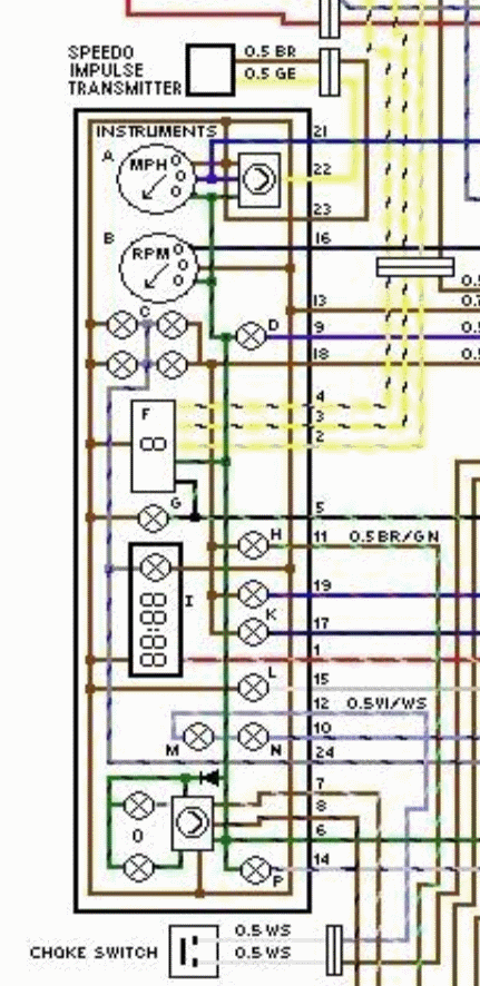
Regarding one of the schematics I'm looking at

First question is on the Oil Warning lamp (H) - clearly the Oil Pressure sense is a (-) input - yet the schematic above shows what should be the high side of that lamp connected to 'ground'
Mistake? Surely should be connected to the Green/Black (+) ?
Next are the M (choke) and N (overtemp) lamps - I presume there should be a connection where the connection between two lamps crosses the green/black trace?
(i.e. a connection 'dot' at that intersection)
And therefor those inputs on 12 & 10 are also (-) triggers.
And contrary to my earlier perception, it looks like the 'charge' signal is also (-) as is 'lamp module'
Edit - I see by looking at other diagrams that indeed that one I posted above is in error and should be as I deduced. Would not surprise me if it came from Haynes, I find issues with their schematics frequently!
I see a number of users with the 2853 Acewell
The only available (-) inputs warning lamps for that gauge are the Oil and Neutral - the only other 'spare' one (besides the turns and the hi beam) is the 'hazard' warning, but the logic for that lamp requires a (+)
Edit - this is yet another documentation error, this time from Acewell - the Hazard Lamp is in fact a '-' input also.
obviously the Neutral is required: are users combining all of those other warning lamps (Oil, Overtemp, Charge, choke, lamp monitor) into that Oil indicator?
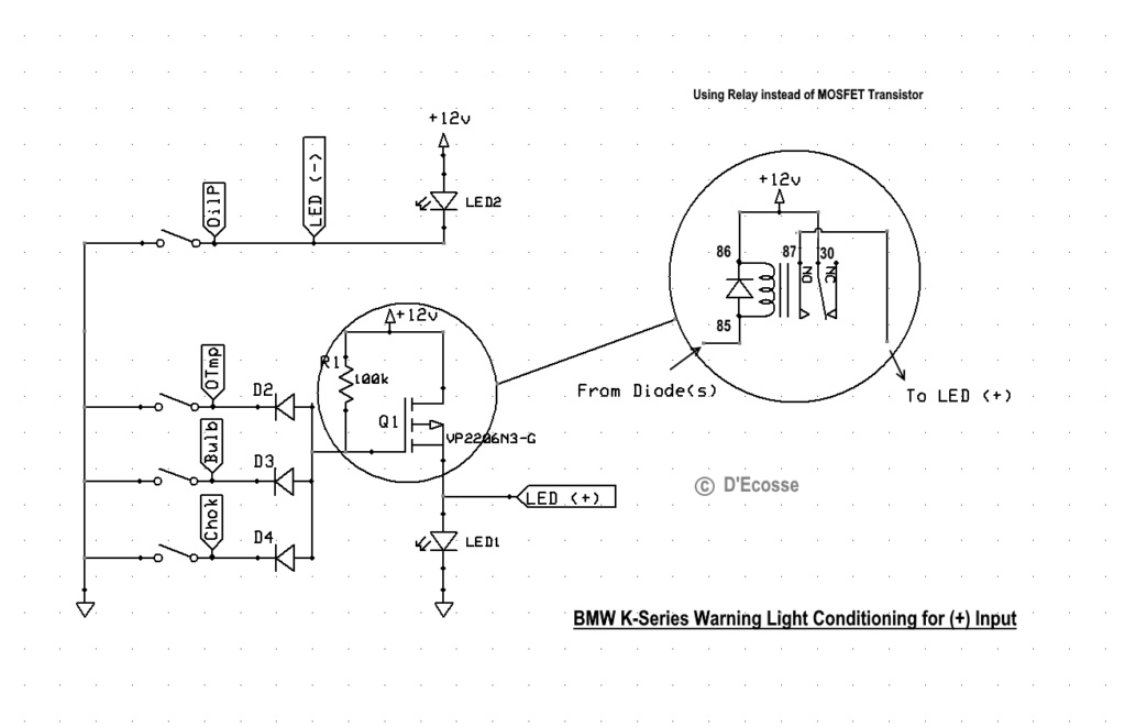
I see on the BEP2.0 schematic that they have multiplexed these signals via diodes into a common connection (as well as providing independent outputs) but again, that will require a (-) input on the instrument
If you wanted to use the 'Hazard' as an alarm, it would required a transistor (or relay) to switch the logic to (+) be able to utilize that.
The TGPI has no provision for this multiplexing so you would have to do this diode-multiplexing externally (in which case you could add the transistor if you wanted to use the (+) input of the hazard alarm light)
So it appears with the 2853 you are stuck with having one warning lamp (oil) for all those functions - so I guess if you have a problem you just panic, stop then try to figure out which one it is!
Incidentally what function ARE 2853 users using that 'hazard' input to display?
I think for the application I'm assisting with, looks like what might be best is to use the in-instrument oil indicator as intended solely for that purpose and have additional (external) LEDs for Overtemp and Charging* - don't think the others worth bothering with, or individuals could add additional LEDs as they choose.
The 'hazard' indicator will have another purpose (in conjunction with a Key-Less system)
* as an alternative to using the OEM charging signal, I personally use this little device - very nice little product, compact and inexpensive
http://www.sparkbright.co.uk/sparkbright-eclipse-battery-voltage-monitor.php
http://www.sparkbright.co.uk/sparkbright-monsoon-battery-voltage-monitor.php (non adjustable display intensity - only marginally cheaper)
I prefer the 5mm LED size myself - see the notes about the control pcb for that one vs the bigger sizes. But the smaller ones are just nicer for my taste.
That of course only addresses the display - you must install a 50 ohm 3W resistor between Ignition Power (Green/Black) and the Blue Wire from the Alternator field coil - this is necessary to ensure the field coil is adequately charged at alternator start-up.
Last edited by D'Ecosse on Fri Jul 20, 2018 9:12 pm; edited 4 times in total


