FWIW here's the way I've just balanced a set of throttles myself. Everyone will have their own equal/better way of doing this, but throttle balancing seems to keep cropping up on this project, so I though an extra 'take' on the whole topic might be of use to the OP:
Theory:
The sort of screw-twiddling balancing that we're doing is essential for smooth tickover and for pickup from low revs. Forget medium to high revs, the throttles will always be matched well enough for that anyway, and there just isn't enough 'twiddle' to unbalance things at high openings.
At small throttle openings (i.e. tickover - 2000rpm-ish) the vacuum on the engine side of the throttle plates is so high that inconsistencies between the tiny openings around the throttle plates can cause an imbalance. This is why, despite the best manufacturing tolerances, some manual adjustment is needed to get it just right. This also caters for wear during the lifetime of the bike. Two adjustments are provided, and these just about enable adequate balancing over the range required.
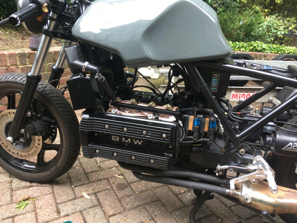
1: Inter-throttle linkages: The 'do-not-touch' blue-painted screws. These are the main way of balancing the throttles. Their purpose is to align the throttle plates with each other so that they all open together by the same amount. The screws are factory set, probably using a flow bench to give an optimum setting throughout the tickover - low revs range. However, once the throttle plates are more than a quarter open, then the sort of small variations you can achieve with the DNT screws start to have no noticeable effect on air flow.
2: Brass bypass screws: at tickover the throttle plate mechanism comes to rest on the throttle stop screw. The purpose of the throttle stop screw is to leave the throttle plates fractionally open so's a tiny amount of air can get past and allow the engine just enough to tickover. If the DNT screws have already been correctly set to give optimum balance through the low rev range, then the chances are that they won't be perfectly balanced when the throttle plate mechanism is resting on the throttle stop screw. It is also the case that an acceptable, balanced tickover would be quite hard to achieve from an engineering perspective with the throttle plates alone. For this reason we have a set of bypass screws, whose purpose is to 'trim' the respective flows past the throttle plates at tickover.
Practice:
Check and eradicate all air leaks as far as possible. Usual suspects are the throttle-to-manifold rubbers, especially if they have been dismantled. Sealant is usually necessary. The high intake vacuum, especially on tickover will exploit the tiniest of leaks and make the whole balancing thing impossible - but not until after you've wrecked all your careful base settings by trying to twiddle an air leak out of the system. That never works btw.
Close the brass bypass screws right down, you'll probs have to hold the throttles open by hand to keep it ticking over. You are now working only with the throttle plates/DNT screws and nothing else.
Rev the engine a bit to see how the vacuum gauges behave. Adjust the DNT screws - each screw controls the relationship between the two throttle plates adjacent to it. Don't worry about tickover speed, what you're aiming for is level readings across all throttles, particularly as you 'rev' the engine a bit. If one or more throttles doesn't behave, then you've got an air leak somewhere.
Once the throttles are all level the DNT screws are set forever and you'll not be touching them again. However, you are going to have to do something with the throttle stop screw. This is okay, because the throttle stop screw only moves the throttle plates in unison, which is fine and won't upset any balance. Anyway, you'll have to adjust it because at this point the thing will either be revving too high with the throttle closed, or not revving enough. Adjust the throttle stop screw to solve this, roughly.
Now it's the turn of the brass bypass 'trim' screws. Open them each by your favourite amount: either one full turn or one and a half turns or whatever. You might then have to back the throttle stop screw off a bit to get tickover back down, to offset the extra air that you've now allowed in by opening the brass screws.
Twiddle away with the brass bypass screws to get even vacuum readings. Try to keep the bypass screws around one turn open, since this is the where their tapered seat principle works best.
Next is tickover speed. What you are actually doing is combining the two air flows (air flowing past the throttle plates, and air flowing past the bypass screws) to give the correct tickover speed. If everything is working correctly, then it should be possible to set the throttle stop screw to achieve a correct tickover speed, with the brass screws each around one turn out.
Remember this: any difficulty/misbehaviour will almost always be down to an air leak somewhere, remember?


 Re: Tuning My K100 Fri Jun 21, 2019 6:41 am