1

 k100 electric screen fitting advice please Sat Jun 09, 2012 5:27 pm
88
Life time member

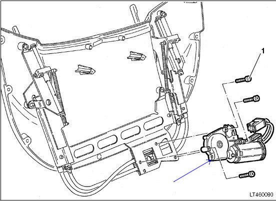
I have been following Crazy Frog's pictures for the k100 bracket modification to accomodate the screen wormdrive casings but one of the drives is fouling the left fairing mount. the only solution seems to be to let the bracket run between the worm drives. I know this is going to be more difficult when the frame is fixed to the bike. the drive casing is really strong and wont allow me to bend it out of the way but it looks like it is not on its original path.
Left side....

right side - neat fit, very little needed to be removed....

sorry for the small pics but I'm having trouble uploading the bigger ones.
88KE
Left side....
right side - neat fit, very little needed to be removed....
sorry for the small pics but I'm having trouble uploading the bigger ones.
88KE
__________________________________________________
 88....May contain nuts!
"The world is a book and those who do not travel read only one page." - St. Augustine from 1600 years ago & still true!
K1 - 1989 - AKA Titan (unique K1/K1100RS hybrid by Andreas Esterhammer)
K1100RS - 1995. AKA Rudolf Von Schmurf (in a million bits)
K100RS - 1991 AKA Ronnie. Cafe racer project bike
K75RTP - 1994
K75C - 1991 AKA Jim Beam. In boxes.
K1100LT 1992 - AKA Big Red (gone)
K100LT - 1988 - AKA the Bullion brick. Should never have sold it.