1

 Wiring in non-BMW handlebar switches Sat Jul 11, 2015 4:35 pm
Dai
Life time member

Before you go any further, you NEED to be aware of the following problem: BMW handlebars are 22.00mm diameter and everybody else uses 22.22mm (7/8") diameter. This means that fitting ANO switches to BMW bars means that you cannot fully tighten them up. There are two solutions to this. On the older metal-cased switches, one turn of insulating tape around the bars will suffice to take up the gap and allow the switches to be tightened. Once the switch is in-situ you can trim the visible edges of the tape with a sharp craft knife blade. The second solution for modern switches involves a drill and a 4.5mm drill bit. Modern switches all seem to come with a peg in one half of the shell that prevents the switch cluster from rotating. Be absolutely sure that you will never want to move the switch cluster from the position you think you want it to be before drilling the handlebars. You can also go for a 'hybrid' setup by removing the peg and using the insulating tape trick. There is a downside to this: the shells are very flimsy (I think this is why they use the peg trick) so it's very easy to overtighten the shell in an attempt to stop it rotating. If you strip the threads (yes, I have (sigh)) there is usually enough room to carefully tap out from 5mm to 6mm.
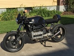
I've muttered about writing this up for the last couple of months, so it's about time I did it. It's mainly aimed at the cafe-racer crowd who might want to change the master cylinder to improve the braking or so they can change the brake calipers too. In my case I've had lifelong restricted movement in both wrists and both thumbs and I was finding the BMW paddles downright painful to operate at times. There are two things you need to know before considering this:
1. You will lose the self-cancelling indicators
2. You may or may not lose the hazard indicators. This depends on whether you have the switch fitted to the crashpad and also whether the replacement switches are European (with headlight on/off) or elsewhere (headlight always on). From 2003 onwards all European bikes are also headlights always on.
3. If you have a naked K or an RS (i.e. narrow bars) your choice is severely restricted to late-Seventies to mid-Eighties Honda handlebar switches with the built-in clutch bracket because there isn't the room to mount a separate clutch and switch. The 'bars are around 2" (50mm) too narrow and a separate clutch bracket causes the cable adjuster to foul the instrument housing. The only exception to this is if you're mounting an aftermarket speedo which will allow more room for the clutch cable to sweep round.
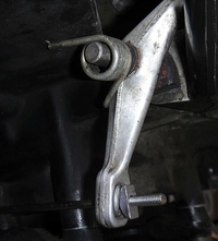
There is a second consideration with the narrow bars too; you will need to figure out some way of mounting a new choke mechanism. On LFB I sorted this by drilling a hole below the indicator switch contacts and mounting the choke mechanism from a Yamaha FZ750 underneath. LFB's lefthand switch is off a mid-Eighties CB250:
http://www.simpilot.net/~sc/brick/sw0.jpg
http://www.simpilot.net/~sc/brick/sw1.jpg
Choke mechanism:
http://www.simpilot.net/~sc/brick/sw2.jpg
[Another edit] Quite a few modern switches now have a fast idle (choke) lever built in to the l/h switch. Since I originally wrote this I've successfully used one of these on LFB after a major winter overhaul that included making a complete new loom. It happened to be from a Triumph Sprint, but of course any switch that has the fast idle lever will do. The downside, as above, is that you'll need to make your own cable. If you do go this route, try and get a switch that still has the fast idle cable attached because most switches sold on ebay come without the brass/plastic lead-in. Failing that, search ebay for 'cable end throttle/choke' and be sure that you get the correct one for the switch you have. [End another edit]
The righthand switch is off a very early CB750 - note the headlight on/off direction is reversed compared to today's switches. The master cylinder is from a Suzuki 1200 Bandit and the reservoir is a Chinese thing.
http://www.simpilot.net/~sc/brick/sw3.jpg
http://www.simpilot.net/~sc/brick/sw4.jpg
Last warning for the narrow bars: when hunting for righthand Honda switches you do NOT want one from a CDI-equipped bike. That type has the kill switch MAKE to kill the ignition system but the BMW requires a BREAK to do the same job. You can always ride around with the killswitch pointing to off...
[Another edit 2] Ditto the comment above regarding lefthand switches; I have successfully fitted a modern righthand switch from a Triumph Daytona to LFB. If you are doing this in the UK and you want the ability to turn the headlight off and just have a pilot light, the law changed in 2013 so that headlights are permanently on as per Europe and the USA. Consequently you need a pre-2013 righthand switch. [End another edit 2]
When hunting for switches you want the following:
Righthand (Europe) - start, kill and headlight off/pilot/on
Righthand (elsewhere) - start and kill (may have hazards in place of the headlight on/off).
Lefthand - horn, flash (passing), high/dip and indicators.
You will also need a wiring diagram from the donor bike(s). You only need this to identify which colour wire does which job and nothing more. The first diagram below is the standard BMW wiring loom - it only shows the areas we're interested in. Connector 1 is the connector block on the left side of the frame that goes to the left handlebar switch. Connector 2 is the connector block on the right side of the frame that goes to the right handlebar switch. How you deal with cutting and replacing wires through these blocks is entirely up to you. My prefence would be to cut them off completely and fit new Molex connectors.
http://www.simpilot.net/~sc/brick/brick_normal.bmp
The second diagram uses Suzuki GSXR 1300 Hayabusa switches for both left and right sides and has no headlight on/off switch.
http://www.simpilot.net/~sc/brick/suzuki_nh.jpg
Whatever switches you use, there are going to be some standard changes in the original BMW loom. In the no headlight switch situation you need to connect the BMW green/blue wire (headlight power feed) across the BMW slate/blue wire (pilot and tail) and the BMW yellow/white wire (headlight feed). If the no headlight switchblock has a hazard switch then you will need to crossfeed to the indicator switch on the new lefthand switchblock as shown above.
Note that not all of the original BMW wires are re-used.
For all replacement switches, locate the BMW flasher relay and unbolt it. Disconnect the relay from the relay block and see how much you can sell it for on Ebay. Under the relay block itself cut and insulate the following two wires:
blue/black
blue/red
This looks counter-intuitive because these are the indicator feeds but the way they run through the loom (one to the left handlebar and one to the right handlebar) means that they are not re-usable from this part of the loom. You will need to run new wires. Also, cut but don't insulate the following two wires:
green/brown
brown
You're going to re-use both of them.
This isolates the original indicator circuit. Now, screw the relay block back in. Depending on your preference for indicators, the replacement indicator relay can be the normal tungsten filament three-pin type or an LED three-pin type. Don't try to use a two-pin bi-metallic type because I'm not sure it will work. On the replacement indicator relay connect the green/brown wire to pin 49 and the brown wire to pin 31. Pin 49a goes to the indicator switch feed on the leftside switchblock.
The simplest place to pick up the indicator feeds is at the rear indicators and then run them up the bike.
The third diagram uses a Suzuki GSXR 1300 Hayabusa switch for the left side, an early Suzuki GSF 600 Bandit switch for the right side and has a headlight on/off switch. Note here that the GSF pilot and headlight circuits have different feeds (pilot is blue/orange, headlight is orange/red), so they both need to go to the BMW light feed (green/blue)
http://www.simpilot.net/~sc/brick/suzuki_wh.jpg
Lastly, just to show I'm not obsessed with Suzukis, the same mod done with the Honda switches that I'm using. Note that here, the Honda black/white and black wires feed to the BMW green/blue light feed. However, there is also a second Honda black wire that provides power to the pilot/headlight switch. I hope you possess a multimeter...
http://www.simpilot.net/~sc/brick/honda_wh.jpg
I've muttered about writing this up for the last couple of months, so it's about time I did it. It's mainly aimed at the cafe-racer crowd who might want to change the master cylinder to improve the braking or so they can change the brake calipers too. In my case I've had lifelong restricted movement in both wrists and both thumbs and I was finding the BMW paddles downright painful to operate at times. There are two things you need to know before considering this:
1. You will lose the self-cancelling indicators
2. You may or may not lose the hazard indicators. This depends on whether you have the switch fitted to the crashpad and also whether the replacement switches are European (with headlight on/off) or elsewhere (headlight always on). From 2003 onwards all European bikes are also headlights always on.
3. If you have a naked K or an RS (i.e. narrow bars) your choice is severely restricted to late-Seventies to mid-Eighties Honda handlebar switches with the built-in clutch bracket because there isn't the room to mount a separate clutch and switch. The 'bars are around 2" (50mm) too narrow and a separate clutch bracket causes the cable adjuster to foul the instrument housing. The only exception to this is if you're mounting an aftermarket speedo which will allow more room for the clutch cable to sweep round.
There is a second consideration with the narrow bars too; you will need to figure out some way of mounting a new choke mechanism. On LFB I sorted this by drilling a hole below the indicator switch contacts and mounting the choke mechanism from a Yamaha FZ750 underneath. LFB's lefthand switch is off a mid-Eighties CB250:
http://www.simpilot.net/~sc/brick/sw0.jpg
http://www.simpilot.net/~sc/brick/sw1.jpg
Choke mechanism:
http://www.simpilot.net/~sc/brick/sw2.jpg
[Another edit] Quite a few modern switches now have a fast idle (choke) lever built in to the l/h switch. Since I originally wrote this I've successfully used one of these on LFB after a major winter overhaul that included making a complete new loom. It happened to be from a Triumph Sprint, but of course any switch that has the fast idle lever will do. The downside, as above, is that you'll need to make your own cable. If you do go this route, try and get a switch that still has the fast idle cable attached because most switches sold on ebay come without the brass/plastic lead-in. Failing that, search ebay for 'cable end throttle/choke' and be sure that you get the correct one for the switch you have. [End another edit]
The righthand switch is off a very early CB750 - note the headlight on/off direction is reversed compared to today's switches. The master cylinder is from a Suzuki 1200 Bandit and the reservoir is a Chinese thing.
http://www.simpilot.net/~sc/brick/sw3.jpg
http://www.simpilot.net/~sc/brick/sw4.jpg
Last warning for the narrow bars: when hunting for righthand Honda switches you do NOT want one from a CDI-equipped bike. That type has the kill switch MAKE to kill the ignition system but the BMW requires a BREAK to do the same job. You can always ride around with the killswitch pointing to off...
[Another edit 2] Ditto the comment above regarding lefthand switches; I have successfully fitted a modern righthand switch from a Triumph Daytona to LFB. If you are doing this in the UK and you want the ability to turn the headlight off and just have a pilot light, the law changed in 2013 so that headlights are permanently on as per Europe and the USA. Consequently you need a pre-2013 righthand switch. [End another edit 2]
When hunting for switches you want the following:
Righthand (Europe) - start, kill and headlight off/pilot/on
Righthand (elsewhere) - start and kill (may have hazards in place of the headlight on/off).
Lefthand - horn, flash (passing), high/dip and indicators.
You will also need a wiring diagram from the donor bike(s). You only need this to identify which colour wire does which job and nothing more. The first diagram below is the standard BMW wiring loom - it only shows the areas we're interested in. Connector 1 is the connector block on the left side of the frame that goes to the left handlebar switch. Connector 2 is the connector block on the right side of the frame that goes to the right handlebar switch. How you deal with cutting and replacing wires through these blocks is entirely up to you. My prefence would be to cut them off completely and fit new Molex connectors.
http://www.simpilot.net/~sc/brick/brick_normal.bmp
The second diagram uses Suzuki GSXR 1300 Hayabusa switches for both left and right sides and has no headlight on/off switch.
http://www.simpilot.net/~sc/brick/suzuki_nh.jpg
Whatever switches you use, there are going to be some standard changes in the original BMW loom. In the no headlight switch situation you need to connect the BMW green/blue wire (headlight power feed) across the BMW slate/blue wire (pilot and tail) and the BMW yellow/white wire (headlight feed). If the no headlight switchblock has a hazard switch then you will need to crossfeed to the indicator switch on the new lefthand switchblock as shown above.
Note that not all of the original BMW wires are re-used.
For all replacement switches, locate the BMW flasher relay and unbolt it. Disconnect the relay from the relay block and see how much you can sell it for on Ebay. Under the relay block itself cut and insulate the following two wires:
blue/black
blue/red
This looks counter-intuitive because these are the indicator feeds but the way they run through the loom (one to the left handlebar and one to the right handlebar) means that they are not re-usable from this part of the loom. You will need to run new wires. Also, cut but don't insulate the following two wires:
green/brown
brown
You're going to re-use both of them.
This isolates the original indicator circuit. Now, screw the relay block back in. Depending on your preference for indicators, the replacement indicator relay can be the normal tungsten filament three-pin type or an LED three-pin type. Don't try to use a two-pin bi-metallic type because I'm not sure it will work. On the replacement indicator relay connect the green/brown wire to pin 49 and the brown wire to pin 31. Pin 49a goes to the indicator switch feed on the leftside switchblock.
The simplest place to pick up the indicator feeds is at the rear indicators and then run them up the bike.
The third diagram uses a Suzuki GSXR 1300 Hayabusa switch for the left side, an early Suzuki GSF 600 Bandit switch for the right side and has a headlight on/off switch. Note here that the GSF pilot and headlight circuits have different feeds (pilot is blue/orange, headlight is orange/red), so they both need to go to the BMW light feed (green/blue)
http://www.simpilot.net/~sc/brick/suzuki_wh.jpg
Lastly, just to show I'm not obsessed with Suzukis, the same mod done with the Honda switches that I'm using. Note that here, the Honda black/white and black wires feed to the BMW green/blue light feed. However, there is also a second Honda black wire that provides power to the pilot/headlight switch. I hope you possess a multimeter...
http://www.simpilot.net/~sc/brick/honda_wh.jpg
Last edited by Dai on Sat Nov 11, 2023 7:20 am; edited 4 times in total
__________________________________________________
1983 K100 naked upgraded to K100LT spec after spending time as an RS and an RT
1987 K100RT
Others...
1978 Moto Guzzi 850-T3, 1979 Moto Guzzi 850-T3 California,1993 Moto Guzzi 1100ie California
2020 Royal Enfield Bullet 500